Board index

My Home Page

PilotOdyssey.com By hoser...


PilotOdyssey.com Chat Room

PilotOdyssey.com Photo Album

* Login   * Register * FAQ
http://www.pilotodyssey.com/PO/adm/images/imagemenu/smiley_cool.png PilotOdyssey.com Chat    http://www.pilotodyssey.com/PO/adm/images/imagemenu/find.png PilotOdyssey.com Google Search    http://www.pilotodyssey.com/PO/adm/images/imagemenu/emoticon_tongue.png FL400 Parts    http://www.pilotodyssey.com/PO/adm/images/imagemenu/emoticon_grin.png FL350 Parts    http://www.pilotodyssey.com/PO/adm/images/imagemenu/emoticon_evilgrin.png FL250 Parts    http://www.pilotodyssey.com/PO/adm/images/imagemenu/emoticon_unhappy.png Admin Email   
It is currently Mon Apr 29, 2024 2:09 am

All times are UTC - 5 hours [ DST ]


Post new topic Reply to topic  [ 8 posts ] 
Author Message
PostPosted: Tue Nov 19, 2019 2:02 pm 
Offline

Joined: Mon Nov 11, 2019 9:05 pm
Posts: 134
Location: Dirty Bird, AZ
'Sup Wildcats!

In my project thread (http://www.pilotodyssey.com/PO/viewtopic.php?f=5&t=19593), I promised to make a thread detailing how I do my connectors. Not because anybody asked mind you, but just because I had taken the photos and felt like posting them. So, if this is for you, strap in and hold on tight. If not, the internet is your playground!

The reason I was bothered to do all this was because my little black box of spooky voodoo automagic had broken, the fan would no longer turn on. As part of it's triage, I needed to remove it, and discovered that I had run a length of cable that wasn't very easy to remove. So I decided to add in a new connector, to make the black box it's own easily removable module.

In the following shot, you can see I've gone ahead and removed about 2" of the outer jacket, exposing the wires.

Attachment:
there_are_5_wires_jean_luc.jpg
there_are_5_wires_jean_luc.jpg [ 71.02 KiB | Viewed 1131 times ]


In my case, I used 22 gauge wire. This is on the small end of the spectrum, so I needed 2 sets of strippers. The set on the left are needed to do the crimping, the middle pair for the stripping (wink/nudge) and of course, good old side cutters on the right.

Attachment:
necessary_tools.jpg
necessary_tools.jpg [ 63.21 KiB | Viewed 1131 times ]


If you use a larger gauge wire, you could probably get away with just the single pair of crimper/strippers. It's the very end that's important, the two spots labeled A and B. Those are used to crimp on the terminal that go inside the connectors.

Attachment:
this_is_a_a-b_photo_c.jpg
this_is_a_a-b_photo_c.jpg [ 46.77 KiB | Viewed 1131 times ]


And finally, below is a shot of all the kibbles and bits we will be using. I got these connectors off Amazon, they are available from 1 through 6 pins. Everything on my Honda was within that range, so I highly recommend picking these up. You could even use them to replace factory connectors (which I may). Here's a link to the 5 pin guys I used for this walk through. https://www.amazon.com/gp/product/B01FU6BB92/ref=ppx_yo_dt_b_search_asin_title?ie=UTF8&psc=1

Attachment:
all_the_fiddly_bits.jpg
all_the_fiddly_bits.jpg [ 66.63 KiB | Viewed 1131 times ]


Top
 Profile E-mail  
 
PostPosted: Tue Nov 19, 2019 2:29 pm 
Offline

Joined: Fri Jul 04, 2014 7:33 am
Posts: 1070
I need to get myself some of those kind of crimping tools. I see them at auto zone style places, and other tool places; but I believe the best ones can only really be found at electrical supply shops.

Those crimps are instrumental when re-doing all kinds of wiring harnesses.


Top
 Profile E-mail  
 
PostPosted: Tue Nov 19, 2019 3:02 pm 
Offline

Joined: Mon Nov 11, 2019 9:05 pm
Posts: 134
Location: Dirty Bird, AZ
OK! So got all your kibbles and bits, and tools ready to go? Nothing to it but to do it!

First off, get your wires stripped. You'd be surprised how little you need to remove. Between 1/8" and 3/16" inch. Any more and you run the risk of the wire going inside the terminal, and interfering with the connection, no room for the pin, that sort of thing.

Attachment:
bare_nekked_wires.jpg
bare_nekked_wires.jpg [ 34.6 KiB | Viewed 1126 times ]


In these next 2 shots, you can see where you want the wire to lay in the terminal, as it's in the crimper. This is just to illustrate where you want the wire to be. As you can see, there are 2 sets of tabs, a larger set on the left, and a smaller set immediately to the right. You want the insulation to line up with the edge of the smaller set. It won't look like this while you have the terminal in the tool, but this should give you an idea of how deep you want the insulation to go, as well as how deep the wire should go.

Attachment:
relative_position.jpg
relative_position.jpg [ 37.32 KiB | Viewed 1126 times ]


Attachment:
relative_position2.jpg
relative_position2.jpg [ 36.87 KiB | Viewed 1126 times ]


Here's what it the terminal looks like in the tool. Be sure you start with the smaller crimp, on the conductive substrate (copper/aluminum/etc). So put your terminal in the tool (male or female) and put the smaller of the two tabs into slot 'B'.

Attachment:
start_with_b.jpg
start_with_b.jpg [ 46.43 KiB | Viewed 1126 times ]


Attachment:
terminal_position.jpg
terminal_position.jpg [ 37.27 KiB | Viewed 1126 times ]


Alright, so got your terminal loaded, now you just need to put the wire in to the correct depth, and give it a squeeze! In this shot, I've crimped on the first of the female terminals.

Attachment:
crimp_1_done_in_a_bun_son.jpg
crimp_1_done_in_a_bun_son.jpg [ 32.01 KiB | Viewed 1126 times ]


However, I've made a mistake (kinda) that I need to point out. Since these are waterproof connectors, you ideally should be adding the little silicone collar to the wire, prior to crimping on the terminal. Fortunately they are stretchy, so I was able to slip one over this terminal. All the rest, I put the collar on the wire before stripping and crimping the terminal. If you are doing larger gauges, it can be easier to do it this way (terminal first), so you have a bit of a handle to hold onto.


Top
 Profile E-mail  
 
PostPosted: Tue Nov 19, 2019 3:11 pm 
Offline

Joined: Mon Nov 11, 2019 9:05 pm
Posts: 134
Location: Dirty Bird, AZ
In this next shot, you can see I've now got the terminal loaded into slot 'A', ready to crimp it onto the insulation.

Attachment:
tab_1_in_slot_a.jpg
tab_1_in_slot_a.jpg [ 48.48 KiB | Viewed 1126 times ]


And then again, give it a squeeze!

Attachment:
squishy_squish.jpg
squishy_squish.jpg [ 48.82 KiB | Viewed 1126 times ]


PROTIP! When you are squeezing these crimps, in both slot A and slot B, the terminal will sometimes distort a bit. It tends to bend up/down. While you still have the terminal in the tool, before taking it out, bend the terminal back straight. Otherwise, they can be a pain to straighten with just your fingers, and they HAVE to be straight otherwise they are near impossible to install.

Here's the finished terminal (sans silicone collar)

Attachment:
waa_laa!.jpg
waa_laa!.jpg [ 33.41 KiB | Viewed 1126 times ]


Once you do one, the rest get easier and go faster . Here you can see I've fixed my mistake, and put the collars on all the wires.

Attachment:
its_like_tv_magic.jpg
its_like_tv_magic.jpg [ 41.46 KiB | Viewed 1126 times ]


Top
 Profile E-mail  
 
PostPosted: Tue Nov 19, 2019 3:28 pm 
Offline

Joined: Mon Nov 11, 2019 9:05 pm
Posts: 134
Location: Dirty Bird, AZ
OK, terminals are locked on, time to push them in!

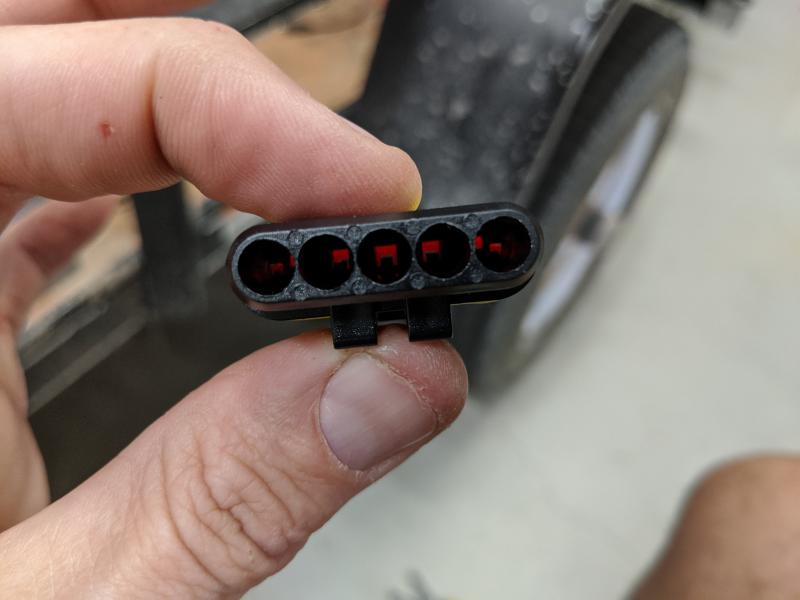
First thing is to orient the plug and the terminal. If you look down in the hole of the connector from the backside (where the terminal will go in) you'll see a small plastic tab sticking up. This is the locking tab. Make note of which way it's pointing. In this shot, it's pointing up.

Attachment:
connector_internal_shot.jpg
connector_internal_shot.jpg [ 36.35 KiB | Viewed 1125 times ]


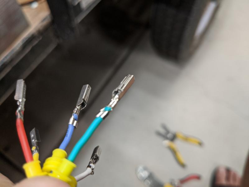
Next step is to orient your terminal. For this, you'll notice there's a pair of ears on the terminal, in this shot they are also pointing up. On the blue wire they are kind of pointing off to the right.

Attachment:
terminal_ear_position_up.jpg
terminal_ear_position_up.jpg [ 29.26 KiB | Viewed 1125 times ]


When you install the terminal into the connector, you want the ears pointing towards the tab. So if you were holding the connector like in the first shot, with the locking tab facing up, you'll need to flip the terminal over, so the ears are facing down. You always want to install with ears facing tab, whether doing the male or female end.

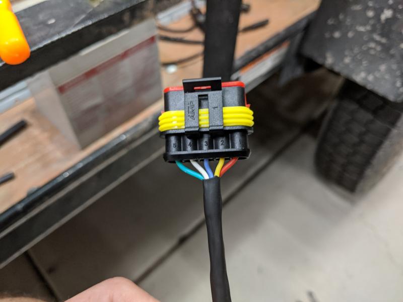
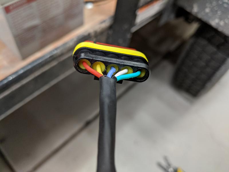
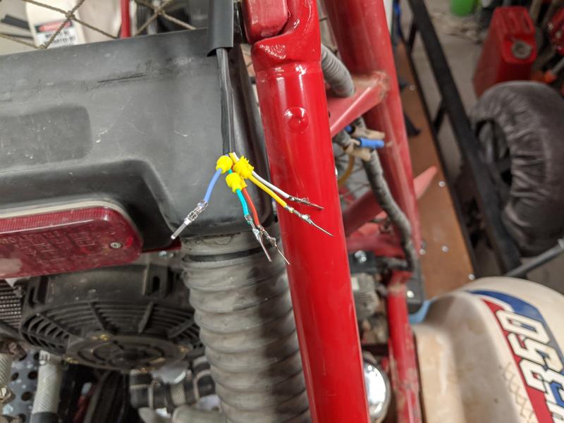
Here's a couple shots of the results on this side. You can see how the silicone collars come into play, making this a waterproof connection.

Attachment:
push_till_click_rinse_repeat.jpg
push_till_click_rinse_repeat.jpg [ 40.54 KiB | Viewed 1125 times ]


Attachment:
silicone_collars_activate!.jpg
silicone_collars_activate!.jpg [ 33.88 KiB | Viewed 1125 times ]


In order to ease installation, I HIGHLY recommend picking up a pair of long, skinny needle nose pliers. These came in a kit I got from the Walmart tool aisle, they are from a HyperTough 5 pack of pliers. These work perfectly for pushing these little buggers in. Word of caution, the female side is always way harder to push in for some reason. Edit Make sure you disengage the red plastic tip on the connector body, that accepts the female terminal. This is a locking tip, there are plastic tabs on either side you gently pry out on, and then it will pull out to a certain point. Edit off Be sure to grip the wire immediately behind the terminal. You want the tip of the pliers to push against the terminal, when it's in the hole. Your grip on the wire is just to guide the connector in, all the pushing should be via the plier tip against the terminal.

Attachment:
long_nose_pliers_must.jpg
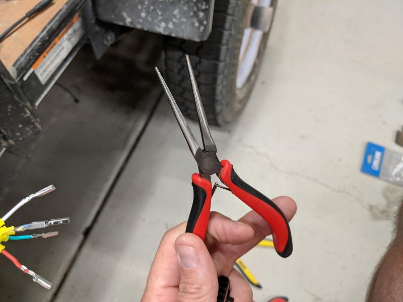
long_nose_pliers_must.jpg [ 42.17 KiB | Viewed 1125 times ]


Moving on, time to repeat the process for the other end, the male side of things. Again, it goes exactly the same, start with silicone collars, strip, crimp with 'B', crimp with 'A'. I've sped up the process, here's the terminals ready to go.

Attachment:
now_do_the_male_side_too.jpg
now_do_the_male_side_too.jpg [ 60.64 KiB | Viewed 1125 times ]


Top
 Profile E-mail  
 
PostPosted: Tue Nov 19, 2019 3:39 pm 
Offline

Joined: Mon Nov 11, 2019 9:05 pm
Posts: 134
Location: Dirty Bird, AZ
Here's a shot of the inside of the male connector. You can see it's got the same plastic tabs (facing up again). The male terminals also have ears, just like the females. Be sure to align things 'tab to ears', and push it on in.

Attachment:
male_connector_tabs.jpg
male_connector_tabs.jpg [ 41.01 KiB | Viewed 1125 times ]


Technically, that would just about cover it. I personally am also a big fan of heat shrink tubing. I currently don't have any tubing large enough to cover the base of these 5 pin connectors, but I did pre-install a sleeve of heat shrink tubing on either end. I was able to use electrical tape (3M Super 33 is awesome) to wrap the base of the connector, and then on down the wire some. Then I use the heat shrink tubing to cover the end of the electrical tape, to keep it from unwrapping. For a smaller connector (4 pins on down) I'll do a series of heat shrink tubing, to transition from the cable/wires to the connector body, giving it a cleaner look and extra protection from bending strain.

This side didn't turn out as nice as I'd hoped, it's thoroughly covered however it looks kinda weird.

Attachment:
janky_wrap_job.jpg
janky_wrap_job.jpg [ 52.23 KiB | Viewed 1125 times ]


The other end turned out much better.

Attachment:
this_side_looks_better.jpg
this_side_looks_better.jpg [ 74.24 KiB | Viewed 1125 times ]


And then it's just a matter of plugging those suckers together. The ultimate 'plug and play' baby!

I hope this is useful to you guys, let me know if you have any questions!


Top
 Profile E-mail  
 
PostPosted: Tue Nov 19, 2019 3:44 pm 
Offline

Joined: Mon Nov 11, 2019 9:05 pm
Posts: 134
Location: Dirty Bird, AZ
ZeroClient wrote:
I need to get myself some of those kind of crimping tools. I see them at auto zone style places, and other tool places; but I believe the best ones can only really be found at electrical supply shops.

Those crimps are instrumental when re-doing all kinds of wiring harnesses.


Agreed, you definitely get what you pay for when it comes to tools. These are just some cheapos I got from Frys Electronics here in PHX, but they do this job just fine :-)


Top
 Profile E-mail  
 
PostPosted: Tue Feb 18, 2020 12:04 pm 
Offline

Joined: Mon Nov 11, 2019 9:05 pm
Posts: 134
Location: Dirty Bird, AZ
Protip! Just the tip! Only for a second!

Cereal, it's actually easier if you pull out the red plastic locking tip, prior to loading the female connectors. My apologies for missing this, I had used the long skinny needle nose pliers to force the connectors in past the red plastic. You still need the pliers to get the square connectors in, but it's WAY easier if you disengage the lock :shock:

Attachment:
freggin_bonehead.jpg
freggin_bonehead.jpg [ 45.98 KiB | Viewed 955 times ]


They also conveniently make it so the tip will only come out *so far* and wait there patiently till you push it back into place. So you won't lose it or forget the orientation, etc.

The male side of things also has a red piece down the barrel of each of them, but it's more of a pin guide. It doesn't do anything to retain the connectors, beyond inhibit depinning.

Now get out there and get crimping!


Top
 Profile E-mail  
 
Display posts from previous:  Sort by  
Post new topic Reply to topic  [ 8 posts ] 

All times are UTC - 5 hours [ DST ]


Who is online

Registered users: Bing [Bot], Google [Bot], Gootjr, Lanix


You cannot post new topics in this forum
You cannot reply to topics in this forum
You cannot edit your posts in this forum
You cannot delete your posts in this forum
You cannot post attachments in this forum

Jump to:  
cron
Powered by phpBB® Forum Software © phpBB Group