Board index

My Home Page

PilotOdyssey.com By hoser...


PilotOdyssey.com Chat Room

PilotOdyssey.com Photo Album

* Login   * Register * FAQ
http://www.pilotodyssey.com/PO/adm/images/imagemenu/smiley_cool.png PilotOdyssey.com Chat    http://www.pilotodyssey.com/PO/adm/images/imagemenu/find.png PilotOdyssey.com Google Search    http://www.pilotodyssey.com/PO/adm/images/imagemenu/emoticon_tongue.png FL400 Parts    http://www.pilotodyssey.com/PO/adm/images/imagemenu/emoticon_grin.png FL350 Parts    http://www.pilotodyssey.com/PO/adm/images/imagemenu/emoticon_evilgrin.png FL250 Parts    http://www.pilotodyssey.com/PO/adm/images/imagemenu/emoticon_unhappy.png Admin Email   
It is currently Sat Apr 27, 2024 10:46 am

All times are UTC - 5 hours [ DST ]


Post new topic Reply to topic  [ 9 posts ] 
Author Message
PostPosted: Wed Dec 09, 2020 1:18 pm 
Offline

Joined: Fri Jan 12, 2007 2:17 pm
Posts: 3620
Location: Wichita ks
Since I decided to play with the front springs to match up with the rear change I thought I would share some graphs. To make it easier to follow and see what I see. I can use these base lines with pre load and No pre load to change the spring stack around to get me where I would like to run it for different areas. The graph shows wheel and shaft one with a little more info so you get the idea. The dual rate line can change in way of cross over spacer effecting the final rate line which will shorten or lengthen the lines adding or subtracting poundage through that range. This will have zero effect on Ride Height. The cross over on the Tender will also effect the final poundage because when it crosses over to the main spring the travel per inch will change. I think you get the idea.


Attachments:
Triple Rate Spring.jpg
Triple Rate Spring.jpg [ 27.41 KiB | Viewed 1387 times ]
Resize of Wheel.jpg
Resize of Wheel.jpg [ 69.76 KiB | Viewed 1387 times ]
Resize of Shaft.jpg
Resize of Shaft.jpg [ 59.85 KiB | Viewed 1387 times ]
Top
 Profile  
 
PostPosted: Wed Dec 09, 2020 3:35 pm 
Offline

Joined: Fri Jan 12, 2007 2:17 pm
Posts: 3620
Location: Wichita ks
Time for some FUN.
As stated above I can change the Cross Over Point on the tender with out upsetting the Ride Height. As long as the change comes after the sprung weight constant. This is the weight supported by the springs. If you look at the graph and the poundage change at cross over 143 pounds. As long as your sprung weight is below this number the ride height will not change. Another Item to take note here is the sag %. The 143 is right at 42%.
So this would not be ideal for this set up and this is why. When the damper (shock) goes into bump or compression your on the main spring already and its rate. so your not at the softer dual rate and then transition to the final rate. So the cross @ 2.0 would not be a good thing for a triple rate. Crossing at 2.5 would allow for a softer rate to roll over bumps then get stiffer. This has other effect on the front wheel load and steering however lets stick to the basics for now. The only advantage would be when it goes into droop via a hole. It would not slam up on to the main spring from the helper and control the rebound with upsetting the rebound built into the shock.
What to do? either increase tender rate and decrease pre load and maintain ride height or add pre load increasing ride height. Remember to keep your Attitude in check.

Now go and look at the previous pics and look at where the 143 is.


Attachments:
Resize of Cross Over Shaft.jpg
Resize of Cross Over Shaft.jpg [ 66.84 KiB | Viewed 1378 times ]
Resize of Cross Over Wheel.jpg
Resize of Cross Over Wheel.jpg [ 68.67 KiB | Viewed 1378 times ]
Top
 Profile  
 
PostPosted: Wed Dec 09, 2020 4:20 pm 
Offline

Joined: Fri Jan 12, 2007 2:17 pm
Posts: 3620
Location: Wichita ks
I marked up a pic to show ya. So with this I get the best of both. Dual Rate on bump and smooth out the compression from droop as if I hit a hole. Now I have not upset my compression or rebound valving. Still room for improvement though. You can see how this can aid in spring choice with out guessing and change the valving accordingly. Lucky me I have high low and rebound and already made valving change based on spring and there rates.


Attachments:
adminded.jpg
adminded.jpg [ 72.92 KiB | Viewed 1376 times ]
Top
 Profile  
 
PostPosted: Wed Dec 09, 2020 4:25 pm 
Offline

Joined: Fri Jan 12, 2007 2:17 pm
Posts: 3620
Location: Wichita ks
Now lets look at the same pic and the Zero Pre Load line. This represent what I was saying.


Attachments:
adminded Zero.jpg
adminded Zero.jpg [ 76.33 KiB | Viewed 1376 times ]
Top
 Profile  
 
PostPosted: Wed Dec 09, 2020 4:49 pm 
Offline

Joined: Fri Jan 12, 2007 2:17 pm
Posts: 3620
Location: Wichita ks
Big question???? Is 712 enough Spring Bottom Out Poundage (BOP). This does include the bottom out bumper and it rate. If we change this out to a stiffer or more progressive rate it impacts the BOP. This is where the stiffer valving come into play however it can only go so far or we blow it apart or break us or our chassis. Or all the above. Keep in mind this is for one shock and there is one on each side and the machine is around 600 and an average rider of 250. with a balance of ??????. See where I am going! also keep in mind we dive it in on one front tire as well. So I test this by hitting a jump cross ways and diving it in. As I do this I adjust the high speed to find a good setting and see where the valving is at. This allows the shock to bottom under valving control and the rebound push the machine back upright in a control faction. If I am close to full high speed I increase valving by one shim stack thickness until I can use the adjuster to around 60% See not rocket science. Harder the hit faster the shaft velocity. You will surprised that a one front wheel landing is just as fast as a g-out or square edge hit. Now we all have felt that and never hit the jump.
The square edge hit can be a rut or tree root etc. anything that would compress the shock to bottom. Its a very fast movement. Did I say I was setting mine for woods ridding, ummmmmm. Yes this can happen in the duns as well even more so now that UTV took over and leave big rutts. Talk about a surprise.

I know enough bable. So with the 143 and we add pre load we can add shaft compression length and greater BOP Not every are requires 45% sag and not recommended unless you have long travel set up. other wise we would look at 20 to 30% with 30% being a max number. 20% on a short shock is about idea. The issue is is does not leave much room for droop out and upsets the chassis. Hench the advantage of long travel.


Top
 Profile  
 
PostPosted: Wed Dec 09, 2020 5:22 pm 
Offline

Joined: Fri Jan 12, 2007 2:17 pm
Posts: 3620
Location: Wichita ks
So a few clicks and here we go. You can see this is nice and linear. For a 30% set up a simple dual rate would do. Just change the tender spring and change the cross over.


Attachments:
Resize of 30% admended.jpg
Resize of 30% admended.jpg [ 65.88 KiB | Viewed 1374 times ]
Top
 Profile  
 
PostPosted: Wed Dec 09, 2020 5:49 pm 
Offline

Joined: Fri Jan 12, 2007 2:17 pm
Posts: 3620
Location: Wichita ks
Did a quick dual rate set up to compare.
I will let a lot of this soak in before going on.


Attachments:
Resize of 37% sag with 240 main.jpg
Resize of 37% sag with 240 main.jpg [ 69.07 KiB | Viewed 1373 times ]
Top
 Profile  
 
PostPosted: Fri Dec 11, 2020 12:34 pm 
Offline

Joined: Fri Jan 12, 2007 2:17 pm
Posts: 3620
Location: Wichita ks
Time to share a couple more pics. This time I took the front pilot works shock and ran a comparison to My shock just changed a couple things.The works shock on a stock pilot set up for dunes and a rider weight of 180. You will notice the that the ride height as gone up over the previous pics and the BOP as well. Even thought the 140# I have been using is not the true number I will use it for this example as well so it is easier to follow. The ride sag # is one of the key points hear as well as BOP. Works as a rule uses 20% in most cases. As mentioned before the droop % when a hole is encountered is what I fell an important issue with the available shaft and wheel travel numbers. This allows the chassis to dive into the next set of rollers and or skips over a set of rollers bumps etc. The front spring set and valving is more aggressive than the works rear set up. I bring this up as it leads to the next part of the conversation on shock set up.

Any way here is some pics to mole over. The shaft on Mine (DCP) is only .5" longer than the works when you look at the shaft graph however when you look at the wheel graph it paints a little different picture. I will not even bother with stock. The works is a great improvement over stock and I fell the best bang for the buck on a stock front end. I did talk with works about my set up when I did it and they would not build me a set because of the rear. They wanted to limited the rear shaft and have me change the ratios and in front change the travel numbers for there shock bodies. I chose not to do that due to the stock mounting point and I wanted to work with in this range. Thought I would add a little back ground info. Axis was a little ummmm as well at first then after talking with them about choices and there ability to cut shock bodies and shafts down to size they said that will work. I just had to remind them that they build custom shocks. I also must say they were good to work with and still have great talks with and they support my set up with parts.

Keep in mind these numbers are for the springs no bottom out bumper has been put into the graph yet. I just add the data series. That's kinda cool to see its effects.


Attachments:
Resize of DCP Works Shaft.jpg
Resize of DCP Works Shaft.jpg [ 66.69 KiB | Viewed 1353 times ]
Resize of DCP Works Wheel.jpg
Resize of DCP Works Wheel.jpg [ 73.17 KiB | Viewed 1353 times ]
Top
 Profile  
 
PostPosted: Mon Dec 14, 2020 8:20 pm 
Offline

Joined: Fri Jan 12, 2007 2:17 pm
Posts: 3620
Location: Wichita ks
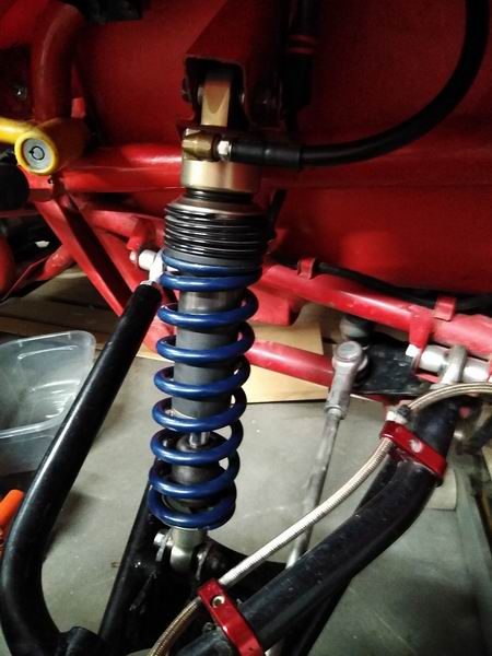
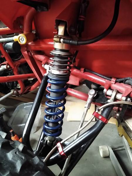
I forgot to load up pics of the dual rate set up. It's the 11 lb/in rate (helper spring) over the 240 main or 11/240. This is a zero pre load set up. I can control the block point of the helper spring as well as change the ride height via the pre load position. This way i can set the sag to about what ever 10 to 50%. The variation of this will be a triple rate set up using 11/350/240 11/350/215 spring sets.

These will come into play as I precede with the topic.

Now that we have an idea on spring rate, travel and loads on the spring it is time to move to the wheel and it rates compared to the springs and how those weird charts work when we enter toe calculate the spring rate.
We discussed motion ratio or leverage ratio what ever you prefer. So now we can compare this to the arms motion ratio that the calculators use. For me they do more harm than good in way of confusion. anyway, I will try to break it down a little so it makes since. I will use an example of the pilot front and try to talk my way though it.


Attachments:
Resize of IMG_20201214_165459073_BURST001.jpg
Resize of IMG_20201214_165459073_BURST001.jpg [ 51.45 KiB | Viewed 1338 times ]
Resize of IMG_20201214_165523261_BURST001.jpg
Resize of IMG_20201214_165523261_BURST001.jpg [ 59.05 KiB | Viewed 1338 times ]
Top
 Profile  
 
Display posts from previous:  Sort by  
Post new topic Reply to topic  [ 9 posts ] 

All times are UTC - 5 hours [ DST ]


Who is online

Registered users: Bing [Bot], Google [Bot], Q, wyeeoddy


You cannot post new topics in this forum
You cannot reply to topics in this forum
You cannot edit your posts in this forum
You cannot delete your posts in this forum
You cannot post attachments in this forum

Jump to:  
cron
Powered by phpBB® Forum Software © phpBB Group