Board index

My Home Page

PilotOdyssey.com By hoser...


PilotOdyssey.com Chat Room

PilotOdyssey.com Photo Album

* Login   * Register * FAQ
http://www.pilotodyssey.com/PO/adm/images/imagemenu/smiley_cool.png PilotOdyssey.com Chat    http://www.pilotodyssey.com/PO/adm/images/imagemenu/find.png PilotOdyssey.com Google Search    http://www.pilotodyssey.com/PO/adm/images/imagemenu/emoticon_tongue.png FL400 Parts    http://www.pilotodyssey.com/PO/adm/images/imagemenu/emoticon_grin.png FL350 Parts    http://www.pilotodyssey.com/PO/adm/images/imagemenu/emoticon_evilgrin.png FL250 Parts    http://www.pilotodyssey.com/PO/adm/images/imagemenu/emoticon_unhappy.png Admin Email   
It is currently Sat Apr 27, 2024 3:10 am

All times are UTC - 5 hours [ DST ]


Post new topic Reply to topic  [ 89 posts ]  Go to page Previous  1, 2, 3, 4  Next
Author Message
PostPosted: Tue Nov 12, 2019 11:32 pm 
Offline

Joined: Mon Nov 11, 2019 9:05 pm
Posts: 134
Location: Dirty Bird, AZ
May 30, 2019:

The time has come to start working on the radiator mount. I've been chewing on this issue for weeks, and this was the design I came up with for the Yamaha radiator.

The only 'permanent' change this mod required, was welding 2 tabs onto the rear down tubes. I elected to put the tabs here, since it's where the bracket/weldment slips into the tube and it's the thickest point. Putting the tabs here put the radiator around 5-6 inches back from the hoop netting, so there shouldn't be any issues with your head bouncing into the radiator.

Attachment:
rad_mount2.jpg
rad_mount2.jpg [ 84.17 KiB | Viewed 19182 times ]


Once the tabs were in place, I was able to hang the radiator with just some angle iron and flat stock:

Attachment:
rad_mount1.jpg
rad_mount1.jpg [ 90.47 KiB | Viewed 19182 times ]


For the lower mount, I re-used the upper seat belt mounts. It only took longer bolts in the mount, and I was able to attach both the seat belt, and the lower radiator mount.


Attachment:
rad_mount3.jpg
rad_mount3.jpg [ 108.83 KiB | Viewed 19182 times ]


Attachment:
rad_mount4.jpg
rad_mount4.jpg [ 80.14 KiB | Viewed 19182 times ]


I was also able to take advantage of the lower mount, and re-purpose it as my pump mount, using two exhaust pipe clamps. Forgive the blurry pic, hopefully you get the idea.

Attachment:
rad_mount5.jpg
rad_mount5.jpg [ 68.59 KiB | Viewed 19182 times ]


Here's the final proof of concept, showing that everything fits! Yay!

Attachment:
rad_mount6.jpg
rad_mount6.jpg [ 96.35 KiB | Viewed 19182 times ]


Overall, this turned the radiator and pump (and eventually the tubing) assembly into a single unit, ultimately attached to the frame via 4 bolts. This made it super easy to remove in the future. :-)


Top
 Profile E-mail  
 
PostPosted: Wed Nov 13, 2019 12:03 am 
Offline

Joined: Mon Nov 11, 2019 9:05 pm
Posts: 134
Location: Dirty Bird, AZ
June 2nd, 2019:

Since I had all these new parts that were still ugly and grey, I figured it was time to finally start painting. I was able to fit all the new radiator mount stuff and the rear down tubes into my blast cabinet. If you were looking for a better view of the lower radiator mount/pump mount, here it is!

Attachment:
blastin_time.jpg
blastin_time.jpg [ 60.86 KiB | Viewed 19181 times ]


Here you can see one of the refinished down tubes (blast cabinet and paint make me the welder I ain't) and another view of the upper radiator bracket. If your curious, the paint is Rust-Oleum, Gloss Sunrise Red (7762830).

Attachment:
i_hate_paint.jpg
i_hate_paint.jpg [ 49.53 KiB | Viewed 19181 times ]


This was also around the time my new plate came! So of course I had to mount it and light it! I was able to mount it using just a piece of 1.125 aluminum angle, as long as the plate. I reused the lower battery box mounting bolts to secure it. I literally just had to cut the angle, and drill 4 holes.

Attachment:
plate_mount1.jpg
plate_mount1.jpg [ 86.34 KiB | Viewed 19181 times ]


In this shot, you can see it doesn't interfere with the spare tank holder.

Attachment:
plate_mount2.jpg
plate_mount2.jpg [ 67.77 KiB | Viewed 19181 times ]


The other goodie I worked on for this weekend was the brake light switches. I'd seen some interesting solutions online, as far as adding brake lights to the Odyssey. I like this solution the best. It's simply a replacement banjo bolt, that has a micro pressure switch embedded.

Attachment:
banjo_switch1.jpg
banjo_switch1.jpg [ 24.62 KiB | Viewed 19181 times ]


Attachment:
banjo_switch2.jpg
banjo_switch2.jpg [ 57.28 KiB | Viewed 19181 times ]


So no muss, no fuss, just replace the two bolts and then bleed the system. Oh and then wire it, but that's for another post :-)


Top
 Profile E-mail  
 
PostPosted: Wed Nov 13, 2019 12:29 am 
Offline

Joined: Mon Nov 11, 2019 9:05 pm
Posts: 134
Location: Dirty Bird, AZ
June 22nd, 2019:

Not a whole lot going on these last 2 weeks, still sitting around waiting on the jug and piston to come back from being bored. In the meantime, I've been keeping myself busy with my new blast cabinet. So pretty much everything that I could remove that had paint, got re-painted. I had also gone ahead and replaced all the wheel bearings and seals (front and rear).

Attachment:
painted_parts.jpg
painted_parts.jpg [ 71.49 KiB | Viewed 19178 times ]


Attachment:
painted_parts2.jpg
painted_parts2.jpg [ 87.64 KiB | Viewed 19178 times ]


It was also around this time that the seat was finally done! Yay!

Attachment:
redone_seat.jpg
redone_seat.jpg [ 36.75 KiB | Viewed 19178 times ]


At this point I start thinking about how I'm going to control all this new stuff, like the pump and fan. Ideally, they would be automated, like in a regular car. But how will I do that, and where do I put it?

This is when I notice this weird bracket that came still attached to the replacement hoop.

Attachment:
weird_bracket.jpg
weird_bracket.jpg [ 81.97 KiB | Viewed 19178 times ]


I checked the shop manual, it's nowhere to be found:

Attachment:
no_bracket.jpg
no_bracket.jpg [ 54.42 KiB | Viewed 19178 times ]


However, it's already gotten me thinking, and I've got a plan!


Top
 Profile E-mail  
 
PostPosted: Wed Nov 13, 2019 3:14 am 
Offline

Joined: Mon Nov 11, 2019 9:05 pm
Posts: 134
Location: Dirty Bird, AZ
July 1, 2019:

NERD ALERT!

Remember I had mentioned I wanted to automate the pump and fan? Well this is how I got started, and what I've come up with.

As far as cooling, I wanted to use a bunch of surface mount relays to enable both automation of triggering the fans and pump on and off independently, but also a manual override for each. I decided on surface mount because they are extra small, and I've seen them take a beating in my kids PowerWheels. I elected to go with relays I got from DigiKey. These are, automotive rated, 15 amp 12v SPDT Panasonic relays. If your interested, the part number is JSM1-12v-5. So far, they are flawless. The pump draws around 1.2 amps under load, and the fan draws about 4.5 amp max.

Here's the piece of phenolic sheet (aka Bakelite) I had cut out to make the start of my shade tree circuit board. You can see I had already mapped out where my relays and fuse holders were going to go, and had predrilled the holes.

Attachment:
phenolic_sheet.jpg
phenolic_sheet.jpg [ 52.58 KiB | Viewed 19174 times ]


Here you can see the pieces being test fit.

Attachment:
relay_mount.jpg
relay_mount.jpg [ 63.89 KiB | Viewed 19174 times ]


The sheet, relays and fuses were all laid out to fit in this water/dust resistant project box I found on Amazon. It comes with it's own plastic standoffs, so all you do is drill holes in the Bakelite sheet to match where they are, and then put a small course screw in.

Attachment:
project_box.jpg
project_box.jpg [ 73.43 KiB | Viewed 19174 times ]


I had to modify the project box further, to accommodate my data and signal connections going in (that's the DB9 socket on top) as well as the main power lines and sensor connectors out the side. You can also see I made a rough aluminum bracket to mount it over top of the rectifier/CDI (Capacitor Discharge Ignition)/coil mount. I wish I had a tig so I didn't have to rivet all things aluminum :-)

Attachment:
initial_wiring.jpg
initial_wiring.jpg [ 75.44 KiB | Viewed 19174 times ]


I reused the rectifier/CDI (Capacitor Discharge Ignition)/coil bolt holes, basically my switch box mount stacks on top of the other mount. I'll agree with Honda that this is an ideal position to get things to and from the Engine and cockpit.

Attachment:
mounted_box.jpg
mounted_box.jpg [ 90.52 KiB | Viewed 19174 times ]


So the way this thing works, it has two relays for each device (pump or fan). The two relays are wired in series, so the normally closed position in the first relay automatically gives power to the '30' pole of the 2nd relay. The first relay then becomes the 'override' relay, and the second is now the 'automated' relay in this design.

The 'override' relay is used to switch power away from the 'automated' relay and directly to the device itself. This relay is tied to a manual switch in the cockpit that the driver can use to activate either device, either the pump or the fan, as needed.

The 'automated' relay is used to just turn the device in question on or off in an automated fashion, based on temperature. The radiator came with a sensor bung already, that I was able to reuse. I found on Amazon a series of thermal switches that all screwed into the same plug. So as I figured out what the right temperature was to trigger things at, I could change out the switch to match the temperature range.

Here's a shot of the sensors I'm talking about.

Attachment:
sensor.jpg
sensor.jpg [ 33.84 KiB | Viewed 19174 times ]


So if your still with me and you are now asking to yourself 'So GrojDad, I can see using a temp sensor to turn the fan on or off, but why the pump too dude?', the answer is I don't have a mechanical thermostat in my cooling system. I drilled and tapped a hole for one of these sensor bungs directly in the head, as close to the exhaust port as I could get. That way, the Engine temp in the water jacket over the exhaust port will decide if the pump should turn on or off. With this design, should I be flying down a snowy mountain for whatever reason, my Engine won't get too cold, the pump will just shut off.

I've since made further improvement to this design, namely adding pulse width modulation (PWM) to the cooling fan. I mentioned that it drew around 4.5 amps when it was on, and as I was designing all this I was concerned I would be overdrawing the charging system when riding at night in the summer. The easiest way to ease up on amp draw with a fan is to just slow the thing down, which is what this PWM speed control lets me do. It basically turns the fan on and off thousands of times a second, more 'off' than 'on' depending on how much you turn the knob (fast to slow). This allows me to control exactly how fast the fan runs, and for how long as it's cooling the radiator.

If I'm not mistaken it's a 6 photo max per post. I'll show you guys the PWM upgrade when I get to the cockpit stuff.

Finally, I've come to realize that Honda used to put out their own incandescent light bar add on back in the day, that was basically a 2nd pair of headlights. So everything I did as far as PWM was super cool, but ended up being moot, the charging system didn't have any issues handling the load, and I was well within tolerances. I still kept it though, because it's cool :-)


Top
 Profile E-mail  
 
PostPosted: Wed Nov 13, 2019 7:55 am 
Offline

Joined: Sun Jan 10, 2010 9:14 pm
Posts: 1779
Location: Ma
Love the posts and info. Keep it coming please.


Top
 Profile  
 
PostPosted: Wed Nov 13, 2019 5:54 pm 
Offline

Joined: Mon Nov 11, 2019 9:05 pm
Posts: 134
Location: Dirty Bird, AZ
July 17th, 2019:

Jug's back baby! Woo! Time to get serious about putting this thing together!

First up, bath time! I got it back straight from honing, so it still had grit and fluid in it. It's like baby's first bath in the sink, so cute just sticking out of the bubbles there....

Attachment:
bath_time!.jpg
bath_time!.jpg [ 45.52 KiB | Viewed 19144 times ]


After a thorough scrubbing and immediate oiling, I turned my attention back to the piston. Here it is, ready to slip in. Please forgive the 'under-rags' my boys outgrew, I figure if they are good enough for my kids bums, they're good enough for this job. :-)

Incidentally, I did have the piston drilled with the exhaust bridge lubrication holes, and also had the exhaust bridge clearance relief work done by the machine shop prior to honing. So it should be good to go.

Attachment:
new_piston1.jpg
new_piston1.jpg [ 86.9 KiB | Viewed 19144 times ]


Here's the two slipped together, so far so good!

Attachment:
match_made_in_heaven.jpg
match_made_in_heaven.jpg [ 89.43 KiB | Viewed 19144 times ]


Almost forgot, better get the reeds in before I get too much further.

Attachment:
p-p-p-powerreeds.jpg
p-p-p-powerreeds.jpg [ 61.17 KiB | Viewed 19144 times ]


After that, it was simply a matter of getting the head studs gooped up with some Optimum Grey and then torquing the nuts down.

Attachment:
head_on_directly_to_forehead.jpg
head_on_directly_to_forehead.jpg [ 90.54 KiB | Viewed 19144 times ]


Once that was done and had cured for 48 hours, it was simply a matter of drilling and tapping the sensor hole, and then screwing down the top plate.

Attachment:
cap_and_sensor.jpg
cap_and_sensor.jpg [ 89.02 KiB | Viewed 19144 times ]


Top
 Profile E-mail  
 
PostPosted: Wed Nov 13, 2019 7:33 pm 
Offline

Joined: Mon Nov 11, 2019 9:05 pm
Posts: 134
Location: Dirty Bird, AZ
July 19th, 2019:

I'm slowly layering parts back in, time to stick the carb in. Ooo she nasty!

Attachment:
nasty_carb1.jpg
nasty_carb1.jpg [ 53.97 KiB | Viewed 19141 times ]


Attachment:
nasty_carb2.jpg
nasty_carb2.jpg [ 54.92 KiB | Viewed 19141 times ]


Remember I had replaced the bowl gasket, the needle, the float and also the regulator/tee thing, as well as replumbed the lines. So why was this thing leaking?

It turns out, I had neglected the bowl drain o-ring. As you can see, it's flat as a pancake and hard as a carp.

Attachment:
bowl_drain.jpg
bowl_drain.jpg [ 51.29 KiB | Viewed 19141 times ]


Attachment:
c_dem_o_rangs.jpg
c_dem_o_rangs.jpg [ 42.82 KiB | Viewed 19141 times ]


Since I had it apart, I also used some Simichrome polish on the needle seat, via a q-tip clamped in the end of my drill. I had previously purchased a float level gauge, so I confirmed that the float height was set correctly. Surely now, the carb will be dry, right?! :-)

In this shot, you can also see the in-line fuel shut off, right in front of the throttle cable. I added that to shut off the fuel during transport, it was piddling on my trailer deck. Since adding that, no more issues.

Attachment:
in_line_shutoff.jpg
in_line_shutoff.jpg [ 89.26 KiB | Viewed 19141 times ]


After that, I got the seat belt top bolts in, including the seat belts. I placed the seat in to keep them clean, it's not attached at this point. I include this shot because it gives you a view of the new and improved light bar. Dangling below it and attached at the sides with the same mounting bolts as the light itself, is the Heads Up Display I added, to keep track of all these new data points!

This is just a teaser of course, I'll cover what's on the other side in more detail. But this ties into the control box I had shown before, half those connections in the DB9 socket are just to monitor the state of the relays.

Attachment:
seat_in-HUD.jpg
seat_in-HUD.jpg [ 94.23 KiB | Viewed 19141 times ]


Top
 Profile E-mail  
 
PostPosted: Wed Nov 13, 2019 8:27 pm 
Offline

Joined: Mon Nov 11, 2019 9:05 pm
Posts: 134
Location: Dirty Bird, AZ
July 28th, 2019

We're coming into the home stretch!! Here you can see my first iteration of plumbing the head/pump/radiator.

Attachment:
itsa_me_mario.jpg
itsa_me_mario.jpg [ 93.96 KiB | Viewed 19137 times ]


I wasn't a fan of using so much brass with all this aluminum, so I nixed this, as well as the layout from the pump to the head.

In this next shot, you can see it's been filed, and is almost ready to go. It just needs the airbox put back on, and it should be ready to test.

Attachment:
lets_get_chilly.jpg
lets_get_chilly.jpg [ 100.53 KiB | Viewed 19137 times ]


Here's a shot from the other side, and in this you can see the in-line temp sensor I included, that leads to the HUD.

Attachment:
temp_sensor.jpg
temp_sensor.jpg [ 101.25 KiB | Viewed 19137 times ]


At this point, I've got everything torqued down, so might as well put the tires back on.

Attachment:
baby_gots_new_shoez.jpg
baby_gots_new_shoez.jpg [ 92.47 KiB | Viewed 19137 times ]


I'm motivated, since the end is near! I also knock out the wiring!

Attachment:
wiring_done.jpg
wiring_done.jpg [ 58.02 KiB | Viewed 19137 times ]


And finally, after all this time, I'm able to start it!! :-)


Top
 Profile E-mail  
 
PostPosted: Wed Nov 13, 2019 9:01 pm 
Offline

Joined: Sun Jul 29, 2018 2:03 pm
Posts: 549
Location: Jerseydale, CA
That was one satisfying first start huh? No starter tun-n-n-n-n-n-n-n-n, no checking things, no issues, how cool!


Question -- I have my doubts about the plastic elbows you used on your cooling system. I feel like they may become brittle pretty quick with all the vibrations and movement on the trail. It's been a few months since you've done this, just curious.


Top
 Profile E-mail  
 
PostPosted: Wed Nov 13, 2019 11:59 pm 
Offline

Joined: Mon Nov 11, 2019 9:05 pm
Posts: 134
Location: Dirty Bird, AZ
Garemie wrote:
That was one satisfying first start huh? No starter tun-n-n-n-n-n-n-n-n, no checking things, no issues, how cool!


Question -- I have my doubts about the plastic elbows you used on your cooling system. I feel like they may become brittle pretty quick with all the vibrations and movement on the trail. It's been a few months since you've done this, just curious.


Ha! Yeah I stood there completely stunned for a sec, if you didn't notice. Then I shook loose and started laughing :-) It was quite awesome, and I was especially thrilled to catch it on camera!

Good question, they actually are automotive heater hose elbows I got on Amazon, Dorman 47061. https://www.amazon.com/dp/B000COB8CI/ref=cm_sw_em_r_mt_dp_U_j9mZDbXM1M5EH So they should be designed to take heat and vibration.

Attachment:
heater_elbow.jpg
heater_elbow.jpg [ 24.03 KiB | Viewed 19131 times ]


As far as longevity, no issues so far. I took a knife and scraped a bit off a spare one, they are glass fiber reinforced. I'd expect them to last quite some time.


Top
 Profile E-mail  
 
PostPosted: Thu Nov 14, 2019 12:21 am 
Offline

Joined: Mon Nov 11, 2019 9:05 pm
Posts: 134
Location: Dirty Bird, AZ
August 9th, 2019:

Not much going on, other then tormenting the neighbors briefly over the span of a week or 2. The first ride is awful, it's way too rich. Over the next couple rides I drop the main down a size, eventually to a 138 and it's much better. I also struggle with idle and these power reeds, fiddling with the air mixture screw. I end up bumping the idle jet from a 45 to a 48, and then set the air mixture screw back to 1.5 turns, and life at idle is sweet again.

Since this lady has had issues with keeping the wheels pointing down, I decide to apply some custom warning stickers I got courtesy of AvE :-)

Attachment:
danger_danger.jpg
danger_danger.jpg [ 80.4 KiB | Viewed 19130 times ]


Attachment:
warning_warning.jpg
warning_warning.jpg [ 116.13 KiB | Viewed 19130 times ]


Also, I'm not sure if this is a symptom of me riding around super rich for a bit or if the issue was the altered airflow now that the head fins are no longer part of the mix or what, however for some reason a section of the airbox melted and bulged out, towards the rivet that's in the muffler.

Attachment:
melty_airbox.jpg
melty_airbox.jpg [ 51.52 KiB | Viewed 19130 times ]


The only thing I can think to do to resolve this is to tuck in a heat shield between the muffler and airbox, riveted to the airbox mount you see there. Unfortunately this results in permanent holes in the existing bracket, however at least my change can still be undone via drilling the rivets out.

Attachment:
heat_shield.jpg
heat_shield.jpg [ 71.21 KiB | Viewed 19130 times ]


I was able to sneak out for a nice and easy ride around the CK launch site. I happened to capture some shots of wild burros!

Attachment:
burros_yo.jpg
burros_yo.jpg [ 79.76 KiB | Viewed 19130 times ]


Attachment:
moar_burros_yo.jpg
moar_burros_yo.jpg [ 109.81 KiB | Viewed 19130 times ]


Top
 Profile E-mail  
 
PostPosted: Thu Nov 14, 2019 12:46 am 
Offline

Joined: Mon Nov 11, 2019 9:05 pm
Posts: 134
Location: Dirty Bird, AZ
August 15th, 2019

Disaster!

Well not quite... I just can't follow my own advise.

I'm in Phoenix remember, so it's 'a dry heat', but it's also super thin air. At this point, my cooling system is a complete unknown, and untuned to boot, I have no idea what sensor should be in which bung. So just about every ride I do at this point is at night.

There's an emergency airfield a couple hours west of Phoenix, along the I10. I've been there before, so I'm familiar with the roads there. It's got a bunch of transmission line maintenance roads nearby, so flat and straight. That should be easy peasy in the dark, with my lightbar, right?

It is! It's great, it's nice and cool, and I have a blast! I zoom around and torment the cows, and come back, and decide to take that 'one more rip' (sounds like familiar famous last words, right?)...

This time I go in a different direction, back towards the 10. Along this particular section, there is a bit of a 's' turn, nothing too dramatic. The road had also been recently grated, and it's got massive banks on either side, at least 3-4 foot tall dirt banks on either side. So I zoom on down this stretch, away from the 's' turn, and find a spot to turn around. I then head on back, fully with the intent of loading up and heading home, and I come up to my dust cloud I had left behind. I wasn't expecting this, and with it being night, visibility went to ZERO at the snap of your fingers. It was very still at that point of the night, with the air and ground temperature equalizing, so no air movement to speak of. So of course I come up to the 's' turn blind, just a little too fast. I squeeze the rear a bit too much, it slides up on a bank, back down again as I overcompensate, and then it whips back over and goes down on the PASSENGERS SIDE!!! GAAHHHHH!!!! Just like before!

Thankfully I'm unhurt, the worst I get is a bump to my left shin. But unfortunately my new-to-me hoop is now squished, and the down tubes (including one with a tab I added) are wonky again.

SON OF A DIDDLY! This was the 5th time I'd driven the dad-gum thing since I finished it! SMH!

Attachment:
GrojDad_haz_teh_dumb.jpg
GrojDad_haz_teh_dumb.jpg [ 93.56 KiB | Viewed 19127 times ]


Clearly my stickers didn't work.

So the whole reason I decided to do this particular adventure on a Thursday night, was because the following day Ryan and I had arranged to float the Salt River. So that definitely made me feel better the following day, floating and drinking for 5 hours on 68 degree water, surrounded by college girls in bikinis...

Attachment:
mah_feetz.jpg
mah_feetz.jpg [ 30.16 KiB | Viewed 19127 times ]


Look, wild horses!!

Attachment:
wild_horses.jpg
wild_horses.jpg [ 113.42 KiB | Viewed 19127 times ]


So, Ryan and I talk about it, and I get the number for the body shop. Back to the frame rack we go...


Top
 Profile E-mail  
 
PostPosted: Thu Nov 14, 2019 1:46 am 
Offline

Joined: Mon Nov 11, 2019 9:05 pm
Posts: 134
Location: Dirty Bird, AZ
August 16th to October 13th, 2019

Waiting on my turn at the frame rack. Plus it's too hot to do anything too crazy, I've got a swamp cooler in my shop but it can only do so much. So life goes on, one of my boys has a birthday, we take a family vacation back east to see my parents, etc. But finally I get word that my turn is coming, and if I want to save money/hours, to go ahead and strip the plastics and mods myself.

So that's what I do!

I don't have a whole lot of photos to show from that procedure, however what I do want to show from that was my recording of my 'headliner', that I haven't mentioned yet.

Remember that heads up display I flashed a shot of at the end of my 'first start' video? Well, I realized that I needed more than my project box, in order to contain everything I wanted for my automated cooling system. So to accommodate everything, I built a headliner out of some 1/8" thick fiberboard I got at Home Depot, one side was chalkboard and the other dry erase whiteboard.

I cut this out to size, and then stuck expanding foam tape on the front and rear end, to seal those up. Then I hung the whole thing via 4 zip ties through holes drilled in the tabs for the roof plate, that connect to some aluminum angle I had riveted to the headliner.

This headliner was big enough and deep enough to accommodate a 4 rocker switch + 2 accessory socket panel, and an array of led lights that act as a dome light! The other side, hidden between the roof plate and the headliner itself, became my 'tech closet' for all my connections.

Here's what it looks with the roof plate removed:

Attachment:
headliner1.jpg
headliner1.jpg [ 82.69 KiB | Viewed 19119 times ]


Attachment:
headliner2.jpg
headliner2.jpg [ 96.37 KiB | Viewed 19119 times ]


Here's what it looks like from the drivers seat. The knob with the green tip on the left is the PWM fan speed control, then the switches go (left to right): fan override, pump override, dome light, light bar. Then the 2 accessory sockets, one is a normal 12v 'cigarette lighter' style socket, the other has 2 USB ports. You can also see the 3 led lights for the dome light, between the light bar and the switch panel. At the top right corner, you can see the other DB9 connector, that's where the control and signal lines run. Next to it is a wire loom, that houses the main power bus lines that feed everything upstairs.

Attachment:
headliner3.jpg
headliner3.jpg [ 53.08 KiB | Viewed 19119 times ]


Here it is from a different angle, also showing the heads up display.

Attachment:
headliner4_and_mah_forehead.jpg
headliner4_and_mah_forehead.jpg [ 55.79 KiB | Viewed 19119 times ]


Here's a shot of the PWM speed control. In this application, I had to desolder the knob itself from the circuit board, and then remotely mount just the knob in the headliner. You can see the little green cube for it on the inside of the headliner. I elected to keep the rest of the board in the project box by the radiator, since it was doing the brunt of the work.

Attachment:
pwm_module.jpg
pwm_module.jpg [ 47.44 KiB | Viewed 19119 times ]


Finally, here's a shot of the heads up display active. It's got two led lights at the top left corner, and then the gauges are (left to right) water temp, tachometer, volt meter.

The two LED lights are tri-color lights, they will switch from red to green to blue. I use these to indicate the current status of the cooling device relays. So when the LED for a given device is green, the device is on standby. When the LED switches to blue, the device went to automated active mode (the sensor triggered it on). If the LED goes red, then that means the override switch has been flipped, and the device is powered on all the time, regardless of temp sensor state. One other very useful thing I've found is with this design, should the LED go out completely, that means I've blown the fuse for that particular device!

Attachment:
hud_active.jpg
hud_active.jpg [ 51.95 KiB | Viewed 19119 times ]


Notice how bright those LED's are? That's intentional, so you can see them during daylight. If you look back at the inside of the headliner, I made another Bakelite circuit board, also holding relays, this time tucked on the underside. Those relays control the brightness of the LED's, depending on whether the headlights are turned on or not. I use the relays to simply add or remove resistors to the ground leg of the status LED circuits. So she even has night mode! :-)


Top
 Profile E-mail  
 
PostPosted: Thu Nov 14, 2019 1:34 pm 
Offline

Joined: Mon Nov 11, 2019 9:05 pm
Posts: 134
Location: Dirty Bird, AZ
October 18th to October 20th, 2019:

She's back! Because I had pre-arranged everything, and had stripped all the plastics off, it only took a couple of hours for them to 1) verify the frame was still straight or else put it back to straight and 2) get the hoop mounts straight enough to accept yet another replacement hoop I got off ebay.

This 3rd replacement hoop wan't in as good a shape as the one it was replacing, however it will do for now. I may take one of these other 2 and salvage all the weldments off, and have a brand new one fabricated.

Here's a shot right when she got back, with her in her undies...

Attachment:
she_back!.jpg
she_back!.jpg [ 89.52 KiB | Viewed 19106 times ]


And here she is fully dressed again!

Attachment:
reassembled.jpg
reassembled.jpg [ 87.29 KiB | Viewed 19106 times ]


Since it's now October and becoming blissfully pleasant outside, I decide to get out her 'winter battery'. I picked this up awhile ago, when I had made the spare gas can holder. The intention was to save as much weight as possible, and be as gentle as I could to those stock shocks. This was also my primary reason for including a volt meter, so I could keep an eye on this thing.

Attachment:
startmeup!.jpg
startmeup!.jpg [ 82.74 KiB | Viewed 19106 times ]


Attachment:
startmeup2.jpg
startmeup2.jpg [ 85.81 KiB | Viewed 19106 times ]


This is not the battery you would find if you were to go to the Shorai website, and put in '85 FL350R. It does match all the stats, as far as Ah, CCA and terminal position. The form factor is different though, and I like it better than what they offer on the Shorai site.

Why you ask? Well, this battery matches the footprint exactly, as far as the original AGM I had. What's different is, it's shorter. That's all. The one the Shorai site recommends is exactly the same height and width, it isnt' the same depth.

So to accommodate this particular battery in the FL350R battery tray, all I had to do was cut a piece of 2x4 to length, and tuck it in under the battery. I had covered the 2x4 with a piece of black duct tape, to make it match. It fit like a glove, like it was designed for it. I can also tell you, this battery in the battery holder like it is in the below shot, weighs over 5lbs less than the stock AGM by itself!

Attachment:
LiFePo_in_tray.jpg
LiFePo_in_tray.jpg [ 76.79 KiB | Viewed 19106 times ]


The Shorai battery comes with a bunch of self-adhesive grey foam pieces, you can see in the above shot. I believe what they want you to do with their intended battery is fill up the back of the battery holder with foam, and then stick theirs in.

I mentioned this is the 'winter battery'. These batteries don't tolerate the extreme heat very well. This particular battery spent the summer in the mini fridge under my drill press, till now. I plan on using this till it gets too hot, and then put it back into storage. I've already picked up a 2nd battery tray to hold my 'summer AGM', so I can just swap the tray/battery, without having to mess with the foam and what not.


Top
 Profile E-mail  
 
PostPosted: Thu Nov 14, 2019 1:40 pm 
Offline

Joined: Sun Jul 29, 2018 2:03 pm
Posts: 549
Location: Jerseydale, CA
I am using that Shorai battery on my FL250. Its probably the best battery on the market as far as I'm concerned.


Top
 Profile E-mail  
 
PostPosted: Thu Nov 14, 2019 5:14 pm 
Offline

Joined: Mon Nov 11, 2019 9:05 pm
Posts: 134
Location: Dirty Bird, AZ
November 8th, 2019:

I've been enjoying my Honda, checking out some new trails around my house. I'm really frustrated with the shocks at this point. I've gone through 2 sets of the dirt cheap fronts, and then get a pair of the nitro fronts to find out the bushing is too small. So I'm back to my factory shocks all around.

I've been researching all along, and was looking at the fox rears at least, when I thought to try reaching out to the gentleman in Bakersfield, to see if he had anything comparable for sale. So I text him my question, and he replies I should call him.

So I pick up the phone, and explain what I've been up to and what I'm trying to accomplish. He replies "you know, I'm a Works dealer, right?" Once I scrape my jaw off the floor, I ask "do you have any", to which he replies "Oh yes, I can order them".

!!!!!!!!

So what changed? Evidently Works is back in business, at least in a fashion. So I've gone ahead and placed an order for all 4 corners. I've also asked to accommodate my tank holder, so my new Works shocks should be tuned to me and my rig :-) They should be here in the next 5 weeks or so.

In the meantime, might as well go beat these factory shocks to death, right? So this weekend, I decide to go visit my friend Joe out at Big Sandy, just outside of Wikieup.

In preparation of going to see him, I decide to mount my latest edition, a shiny new GPS speedometer!

Here's where I decided to mount it.

Attachment:
making_a_spot.jpg
making_a_spot.jpg [ 59.89 KiB | Viewed 19096 times ]


That should do nicely...

Attachment:
nice_shirt_dood.jpg
nice_shirt_dood.jpg [ 67.58 KiB | Viewed 19096 times ]


I ended up having to make a custom bracket to accomodate this, but I followed the same principal as the light bar. There's a piece of rubber between the tube and the bracket, and then I used a couple 'worm gear' style hose clamps, covered in heat shrink tubing to secure it. This is what it looks like as the driver.

Attachment:
mounted.jpg
mounted.jpg [ 65.94 KiB | Viewed 19096 times ]


As I'd mentioned, this is a GPS speedo I got on Amazon https://www.amazon.com/dp/B07KNR7NR7/ref=cm_sw_em_r_mt_dp_U_O0BZDbQ12DT68. It lets you change the backlight colors, so I went with blue. I also got the pod listed in the 'Frequently Bought Together' to mount it. Since it's GPS, I needed to (literally) stick the antenna somewhere. Thankfully they give quite a bit of cable, so I have the extra coiled underneath the roof plate there. It's enough that I can remove the roof plate and set it in the seat. You can see in the bottom left corner the wire loom that brings up the gps signal/ground/power/illumination wires.

Attachment:
gps_receiver.jpg
gps_receiver.jpg [ 64.47 KiB | Viewed 19096 times ]


And then off to Big Sandy we go! It's not a shootout weekend http://mgshooters.com/, however Joe lives very close to the shootout. I go out to see him sometimes during one, and watch them shoot at the tannerite charges at night. It's quite the show from a hillside away.

So the nice thing about the Big Sandy area is the roads are all reasonably well maintained, and there's miles and miles of them. So not too rough on my shocks, but more than enough to start figuring out fuel consumption.

I'm very pleased with the performance of the speedometer. My only complaint is there's no way to access the trip functions while it's mounted, either flushmount or in a pod like I have it. The buttons are both on the back. So I leave it at the default trip setting, which is to reset at key off. I'm thinking about making a 'speedo preserve power' switch, to keep the trip counter going while the rest of the buggy is shut off, like when I stop to use the restroom or something.

And that, is just about that. I'd call that about as current as i can make it, just waiting for my shocks now, and thinking about what I'll be getting into next :-)

Please let me know if you have any questions about anything, or want to see more photos of anything in particular.

Thanks for letting me babble!


Top
 Profile E-mail  
 
PostPosted: Thu Nov 14, 2019 5:43 pm 
Offline

Joined: Wed Jan 21, 2009 10:11 pm
Posts: 3496
Location: houston
Fantastic write up and beautiful job on all the extras you did,wish I had your knowledge and skill! Sorry about the crash but not too much damage thankfully.


Top
 Profile  
 
PostPosted: Fri Nov 15, 2019 9:03 pm 
Offline

Joined: Mon Jul 19, 2010 3:20 pm
Posts: 1718
Location: saskatoon, sk, canada
whoa, my brain hurts lol..all that electrical stuff is way over my head, yes works performance is back in business, I just ordered seals and shafts to rebuild mine. for oil I like the motel 710 at 40:1 with avgas


Top
 Profile  
 
PostPosted: Tue Nov 19, 2019 1:06 pm 
Offline

Joined: Mon Nov 11, 2019 9:05 pm
Posts: 134
Location: Dirty Bird, AZ
Just a quick update, I've been tinkering still with the cooling system, trying to dial in when it switches the pump and fan on and off. This configuration I've settled into, I'm quite happy with.

I realized I never posted a link to the sensors themselves, here you go. Just change the color/style to pick what temp range your after.

https://www.amazon.com/gp/product/B07NC98GHM/ref=ppx_yo_dt_b_asin_title_o02_s00?ie=UTF8&psc=1

So the sweet spot for my configuration, with the sensor in the head over the exhaust port, and the other sensor just above the radiator outlet, is:

Head - 140° on, 125° off
Radiator - 170° on, 155° off

Since I replaced the sensors, of course it's time to go test it, ASAP. So Sunday I took it back to the lake, and rode up the mountains towards CK again.

At first I was leery of just letting it go, not hitting the pump switch and just trusting the old girl to handle things. So from start to about 2-3 miles in, I had the pump on override. After that, I reached up and flipped it off, and the LED went blue! Woo!

Of course after that I'm watching my temp sensor like a hawk, making sure the pump actually was running. But sure enough, it took care of it.

Once I got to the really steep, rough part of my climb, I was delighted to see the fan also cycled on, right at the 168°-170° mark according to my gauge. Not only that, but it cooled it down while still under full load while climbing, and cycled itself off. So if anybody is looking for a radiator recommendation, I give this one 4 thumbs up.

Before, when I was riding around with the pump on all the time, the temp would always stay somewhere between 140°-155°. It seems to like to be cool, so that's why I went with the lower temp head sensor. From there, it was just a matter of matching up the lower value (off temp) of the radiator sensor with the optimal temp (or slightly above) and bingo, it's automagic!!

Once I get through the really steep section, I pull over to use the facilities. I leave the key on to preserve my trip data, and while I'm taking care of my business, the Honda was taking care of hers! I hear the fan cycle itself on, run for a bit, and then cycle off. The pump never stopped running with the key on. Wow!!!

So I keep going, up through the nasty wash part, till I have to flip to reserve. From there I only go another mile or 2 before turning back. The reason for this was I wanted to use up the gas in it, I had also just received a jug of Motul 800 offroad and wanted to see how it did. When I departed, both tanks were full of the old stuff, and I wanted to time it so I was just about empty before going with the new raspberry juice.

I make it back no problems, run it to just about empty on the reserve, and then fill up with the Motul (40:1). Woo-pow! That's a spicy! The old girl sure seems to like the stuff. So I start heading back up towards CK again, just to see if I make it further with the new blend. At this point, I'm still monitoring things, but I've given up on the pump override switch, I'm satisfied it's coming on as it should.

I get to another climb, not the big one but still enough to make the girl grunt a bit, and I notice the fan light flips to blue. I decide to stop for a bathroom break, and also to verify the fan is still spinning as it should.

No fan.

?

So I hit the override switch. Still no fan.

I'm about 10-12 miles from the staging area, it's all down hill from here. So I decide to abort and head back. I don't want to push it and boil over or something like that.

While driving back, I'm still mulling on this issue. I decide it's got to be either the speed control (unlikely) or the 5th relay I had to add on the negative side of the fan output. The reason I needed this 5th relay is because the speed control does not have a common ground, it's isolated. So I used the NC position of the 5th relay to run the negative from the speed control to the fan (override off) and the NO position to run the negative to the common ground (override on).

Last night, I pull off my little black box and take a look. Instantly I see the issue. Some dingleberry enginerd forgot to put a strain relief on the wires coming OUT of the box to the fan/pump (both sets share the same grommet), so things vibrated and rattled loose the negative lead (fan negative going out) off of pin 30 of my 5th relay.

Attachment:
broken_joint.jpg
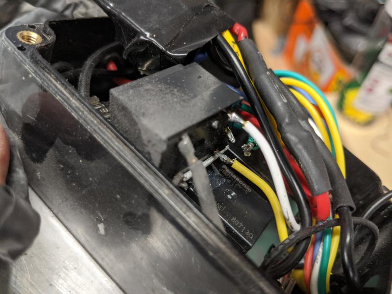
broken_joint.jpg [ 65.14 KiB | Viewed 19031 times ]


Attachment:
broken_joint_2.jpg
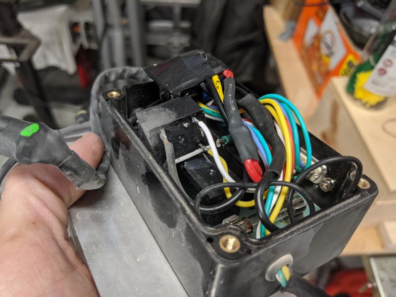
broken_joint_2.jpg [ 65.58 KiB | Viewed 19031 times ]


With that broke, neither the override nor the automated relay are going to work, yet the lights are still on (fuse is good). I mentioned this to Joe, he suggested rewiring it so I see what the true device state is vs what the state of the relays are (on/off). I shot that down as too much work, however I did like the idea. We chat a bit more, and I think I'm going to figure out some sort of verification light that's visible via the rear view mirror. Just something to see the fan is on, since I can't hear it.

I'm not so worried about the pump, since it's going through one of 2 relays. No extra relay or speed control. Plus I also have the temp sensor, I can see independently if things are going sideways. The fan on the other hand, I don't have any sort of back up verification like that, and I think a nice little LED tucked in somewhere that I can see via rear view will do just fine. Something that powers up with the fan, so if I look up at my HUD and see the LED up there is blue, then I can check my mirror to verify that the fan ACTUALLY is on.

So for now, everything is back online. One other mistake the aformentioned dingleberry made was not putting the connector for the speed control knob outside of the headliner. So I ended up having to cut those wires, and put an additional connector. As penance for my failures, I've taken pictures of the whole process, and I'll start a thread in Tech Stuff. Hopefully you guys will find it useful.

Before I close up my black box and remount it with it's spiffy new connector, I get the strain relief added. I also put in some foam, to keep the 5th relay and the speed control in place. I originally had mounted them to the top of the 4 pack of board mounted relays using some double sided tape, however that just wasn't enough. So squishing some foam between the devices and the lid should take care of it.

Attachment:
all_bettah.jpg
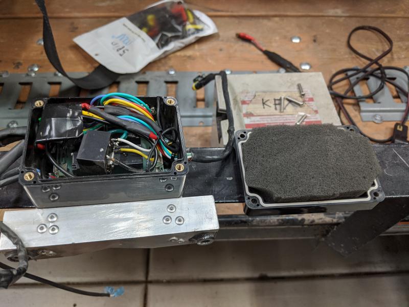
all_bettah.jpg [ 68.65 KiB | Viewed 19031 times ]


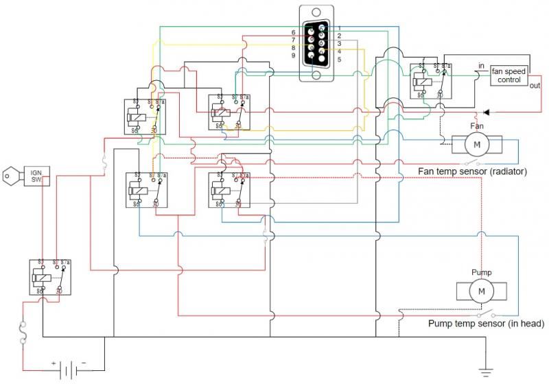
Finally, if anybody here is feeling wild and crazy, and wants to replicate my automation shenanigans, here's a wiring diagram for my black box of spooky voodoo automagic. One thing to keep in mind is the DB9 connector at the top is only there to drive the override switches (pump/fan) and keep an eye on the state of the relays. You could run this box without the override switches or monitoring LED's, just eliminate the DB9 connector and it's leads. I'd advise against it personally though, if you do attempt this design. I believe the more information the better, work smarter not harder! Let me know if you have any questions!


Attachment:
oh_my_god_so_many_wires.jpg
oh_my_god_so_many_wires.jpg [ 47.88 KiB | Viewed 19031 times ]


Top
 Profile E-mail  
 
PostPosted: Tue Nov 19, 2019 5:51 pm 
Offline

Joined: Mon Oct 25, 2004 10:02 am
Posts: 2866
Location: East Peoria IL
You gotta put power steering on that FL350.


Top
 Profile E-mail  
 
PostPosted: Tue Nov 19, 2019 7:51 pm 
Offline

Joined: Mon Nov 11, 2019 9:05 pm
Posts: 134
Location: Dirty Bird, AZ
I could do power steering I suppose, however I don't really see the need personally. It just doesn't tip the needle on my 'need' vs 'cool to do' scale. I think it's fine as is, my only issue as far as steering is the crossbar that's under there to protect the steering linkage. On mine it's getting a bit on the squished side, and starting to expose the linkage (crappy shocks for the most part). I need to address that somehow, guessing I'll have to eventually pull the tub and all that and either replace that bar (most likely) or get it bent back down. While I'm doing all that, I'll probably rebuild the master.

Good suggestion though, keep 'em coming, I'm always open to ideas. :-)


Top
 Profile E-mail  
 
PostPosted: Wed Nov 20, 2019 9:06 am 
Offline

Joined: Fri Mar 18, 2016 6:33 pm
Posts: 945
Location: Rhode Island
Great work here! I need to go back and read this whole thread now. Keep it up! :-)


Top
 Profile E-mail  
 
PostPosted: Fri Nov 22, 2019 5:02 pm 
Offline

Joined: Mon Nov 11, 2019 9:05 pm
Posts: 134
Location: Dirty Bird, AZ
Shocks are here!

Attachment:
whats_behind_door_number_1.jpg
whats_behind_door_number_1.jpg [ 78.52 KiB | Viewed 18973 times ]


Attachment:
yeah_baby!.jpg
yeah_baby!.jpg [ 101.95 KiB | Viewed 18973 times ]


I know what I'm doing after work tonight! :-) ::-:


Top
 Profile E-mail  
 
PostPosted: Fri Nov 22, 2019 5:22 pm 
Offline

Joined: Fri Jul 04, 2014 7:33 am
Posts: 1070
Take your time with the rear shocks. The top needs to run about 1/4 turn or so loose on the shock side else it will bind the shock. The top bolt locks into place with a binding nut behind the frame.

Last I knew (I bought that kit a year ago) they had supplied the wrong thread pitch on either the included bolt or the nylock nut. I forgot which was off but I had to buy the right hardware separately. I told Works and they hopefully corrected this.


Top
 Profile E-mail  
 
PostPosted: Fri Nov 22, 2019 5:26 pm 
Offline

Joined: Fri Jul 04, 2014 7:33 am
Posts: 1070
Pic.

Green circle - You must flat-file your frame enough so that this nut can securely stay put when fully tightened against the bolt. Tighten the NUT - NOT the bolt.

Yellow circle - Keep this bolt about 1/4~1/2 turn loose. Enough so that the SHOCK can SWAY in/out about 1 inch at the BOTTOM eyelet of the shock. The rear shock must be allowed to SWAY or else it will bind and break the eyelet of the shock.


Attachments:
AD1BCDC0-7546-4153-A6DA-9B84CD01CAC8.jpeg
AD1BCDC0-7546-4153-A6DA-9B84CD01CAC8.jpeg [ 34.47 KiB | Viewed 18968 times ]
Top
 Profile E-mail  
 
Display posts from previous:  Sort by  
Post new topic Reply to topic  [ 89 posts ]  Go to page Previous  1, 2, 3, 4  Next

All times are UTC - 5 hours [ DST ]


Who is online

Registered users: Bing [Bot], Google [Bot]


You cannot post new topics in this forum
You cannot reply to topics in this forum
You cannot edit your posts in this forum
You cannot delete your posts in this forum
You cannot post attachments in this forum

Jump to:  
cron
Powered by phpBB® Forum Software © phpBB Group