Board index

My Home Page

PilotOdyssey.com By hoser...


PilotOdyssey.com Chat Room

PilotOdyssey.com Photo Album

* Login   * Register * FAQ
http://www.pilotodyssey.com/PO/adm/images/imagemenu/smiley_cool.png PilotOdyssey.com Chat    http://www.pilotodyssey.com/PO/adm/images/imagemenu/find.png PilotOdyssey.com Google Search    http://www.pilotodyssey.com/PO/adm/images/imagemenu/emoticon_tongue.png FL400 Parts    http://www.pilotodyssey.com/PO/adm/images/imagemenu/emoticon_grin.png FL350 Parts    http://www.pilotodyssey.com/PO/adm/images/imagemenu/emoticon_evilgrin.png FL250 Parts    http://www.pilotodyssey.com/PO/adm/images/imagemenu/emoticon_unhappy.png Admin Email   
It is currently Sat Apr 27, 2024 7:33 am

All times are UTC - 5 hours [ DST ]


Post new topic Reply to topic  [ 22 posts ] 
Author Message
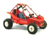
 Post subject: Is this a challenger ?
PostPosted: Mon Nov 26, 2007 4:54 pm 
Offline

Joined: Mon Nov 26, 2007 1:00 pm
Posts: 91
Hi, lee from the united kingdom I am new to this site, I have had a few pilots and now have a pilot with 800 rotax Engine.
Last week I bought this buggy, Someone has told me it could be a challenger which uses odyssey parts, but this has a xenoah 340cc twin Engine.
Any infomation would be welcome.
Thanks Lee.


Top
 Profile  
 
 Post subject:
PostPosted: Mon Nov 26, 2007 5:12 pm 
Offline

Joined: Mon Nov 26, 2007 1:00 pm
Posts: 91
Some photos


Attachments:
Image025.jpg
Image025.jpg [ 54.05 KiB | Viewed 1266 times ]
Image026.jpg
Image026.jpg [ 69.29 KiB | Viewed 1223 times ]
Image027.jpg
Image027.jpg [ 98.12 KiB | Viewed 1223 times ]
Image028.jpg
Image028.jpg [ 94.23 KiB | Viewed 1223 times ]
Image029.jpg
Image029.jpg [ 46 KiB | Viewed 1266 times ]
Image030.jpg
Image030.jpg [ 86.26 KiB | Viewed 885 times ]
Top
 Profile  
 
 Post subject:
PostPosted: Mon Nov 26, 2007 5:16 pm 
Offline

Joined: Mon Nov 26, 2007 1:00 pm
Posts: 91
And more


Attachments:
Image031.jpg
Image031.jpg [ 80.89 KiB | Viewed 1222 times ]
Image032.jpg
Image032.jpg [ 84.85 KiB | Viewed 884 times ]
Image033.jpg
Image033.jpg [ 92.41 KiB | Viewed 884 times ]
Image034.jpg
Image034.jpg [ 94.08 KiB | Viewed 884 times ]
Image035.jpg
Image035.jpg [ 90.67 KiB | Viewed 884 times ]
Image036.jpg
Image036.jpg [ 82.59 KiB | Viewed 884 times ]
Top
 Profile  
 
 Post subject:
PostPosted: Mon Nov 26, 2007 5:50 pm 
Offline

Joined: Mon Dec 15, 2003 2:40 pm
Posts: 22516
Location: Chicago
leegb wrote:
Some photos


It looks Challenger to me here is my old one http://pilotodyssey.com/challengerhome.htm

Pains me to see a full size car battery being carried around in a buggy so small lol


Top
 Profile E-mail  
 
 Post subject:
PostPosted: Mon Nov 26, 2007 10:21 pm 
Offline

Joined: Sat Aug 12, 2006 9:02 pm
Posts: 533
Location: Bellevue WA I OWE Hoser $300.00
Looks like mine (minus the angle iron for a bumper) Yeah its a challenger. Fun machines in my opinion. =)


Top
 Profile  
 
 Post subject:
PostPosted: Tue Nov 27, 2007 3:56 am 
Offline

Joined: Mon Nov 26, 2007 1:00 pm
Posts: 91
Are those rose joints just to the rear of the drive shaft uv standard, they are not fitted to the challenger of hoser. And my front j arms look different, maybe just gussets?


Top
 Profile  
 
 Post subject:
PostPosted: Tue Nov 27, 2007 9:36 am 
Offline

Joined: Mon Dec 15, 2003 2:40 pm
Posts: 22516
Location: Chicago
leegb wrote:
Are those rose joints just to the rear of the drive shaft uv standard, they are not fitted to the challenger of hoser. And my front j arms look different, maybe just gussets?


My Challenger had brackets for the extra links on the rear suspension but were not installed when I bought it I never installed them.

I have seen many variations of J arms for the 250 over the years if you look in the Challenger catalog you might see exactly what they sold with the car. http://pilotodyssey.com/challengercat1.htm

Look at the pic below this is the mod TurboTexas needs to make, I was told the pivot point for the added arm needs to be where the U joint bends.


Attachments:
link mod.jpg
link mod.jpg [ 113.6 KiB | Viewed 775 times ]
Top
 Profile E-mail  
 
 Post subject:
PostPosted: Tue Nov 27, 2007 3:13 pm 
Offline

Joined: Mon Nov 26, 2007 1:00 pm
Posts: 91
Unless I have misunderstud you, The front pivot (visable between the braded hoses) the UJ, and the rose joint at the rear all need to be in line, not where the green line is unless the UJ is plunging which I do not think it is.


Top
 Profile  
 
 Post subject:
PostPosted: Tue Nov 27, 2007 3:52 pm 
Offline

Joined: Mon Dec 15, 2003 2:40 pm
Posts: 22516
Location: Chicago
leegb wrote:
Unless I have misunderstud you, The front pivot (visable between the braded hoses) the UJ, and the rose joint at the rear all need to be in line, not where the green line is unless the UJ is plunging which I do not think it is.


Forget all about the front pivot point only look at the green line and the 2 arrows I added

The way it was explained to me was that the center of the hiem joint in the link should be in the center of the U joint so when the axle angles the added link bends at the same hinge point.

Maybe I am missing something hey LEE!!! what you think?


Top
 Profile E-mail  
 
 Post subject:
PostPosted: Tue Nov 27, 2007 4:15 pm 
Offline

Joined: Mon Dec 22, 2003 9:04 am
Posts: 465
Location: Springfield Ohio
The U-joint needs to be in line with the 2 rod ends, in 3D. That is, draw a line between the center of the balls on the 2 rod ends, place the center of the U-joint on that line.

For a retrofit to a FL350 (with lawyer link steering gear) the front rod end and the U-joint are already set so you need to place the rear rod end on a line extending from the front rod end to the center of the U-joint (actually the line will extend beyond the U-joint).

On Polaris vehicles they some times fix only one side of the U-joint to the drive shaft so that the other side can slide a little and make up for any variation in manufacturing. But to do this you need a splined joint. I do not recommend this on a system using a key.

Other suspension systems may vary, this information is only good for a swing arm or a system where the drive shaft is perfectly in line with the lower arm.


Attachments:
U-joint location - challenger.JPG
U-joint location - challenger.JPG [ 89.12 KiB | Viewed 1130 times ]
Top
 Profile  
 
 Post subject:
PostPosted: Tue Nov 27, 2007 4:20 pm 
Offline

Joined: Wed Dec 24, 2003 12:06 pm
Posts: 1418
Location: San Diego
Hey, it's not lunchtime, what are you doing here?


Top
 Profile  
 
 Post subject:
PostPosted: Tue Nov 27, 2007 4:23 pm 
Offline

Joined: Mon Nov 26, 2007 1:00 pm
Posts: 91
Its evening here in the uk. Were always in front! lol


Top
 Profile  
 
 Post subject:
PostPosted: Tue Nov 27, 2007 4:29 pm 
Offline

Joined: Wed Dec 24, 2003 12:06 pm
Posts: 1418
Location: San Diego
Can you take some closeups (including underneath) of your rear brake caliper, I'd like to see how the hydraulic unit was fit in there.


Top
 Profile  
 
 Post subject:
PostPosted: Tue Nov 27, 2007 4:32 pm 
Offline

Joined: Mon Nov 26, 2007 1:00 pm
Posts: 91
[quote="Lee"]The U-joint needs to be in line with the 2 rod ends, in 3D. That is, draw a line between the center of the balls on the 2 rod ends, place the center of the U-joint on that line.

Yes I agree with Lee (that's Lee not Leegb that's me, too many lee,s) Only thing Is something is not quite in line there the green line does not go through the center of the UJ.


Top
 Profile  
 
 Post subject:
PostPosted: Tue Nov 27, 2007 4:41 pm 
Offline

Joined: Wed Dec 24, 2003 12:06 pm
Posts: 1418
Location: San Diego
Are the u-joints floating on the axle splines or are they clamped down or bolted to them?

If they're floating that would help if there was a little misalignment.


Top
 Profile  
 
 Post subject:
PostPosted: Tue Nov 27, 2007 4:50 pm 
Offline

Joined: Mon Nov 26, 2007 1:00 pm
Posts: 91
Ody_Stable wrote:
Can you take some closeups (including underneath) of your rear brake caliper, I'd like to see how the hydraulic unit was fit in there.

It is not the original caliper, To be honest the brake caliper mount is a total mess and you would not want to copy it. The only thing holding the blue bracket to the main frame that 1 bolt you can see in the pictures, If you were to use the brakes whilst rolling back it would rip it off. I will take a few pictures after I have modified it if you like.


Top
 Profile  
 
 Post subject:
PostPosted: Tue Nov 27, 2007 4:55 pm 
Offline

Joined: Mon Nov 26, 2007 1:00 pm
Posts: 91
Ody_Stable wrote:
Are the u-joints floating on the axle splines or are they clamped down or bolted to them?

If they're floating that would help if there was a little misalignment.

I assume they are clamped because some run them (like hosers) without the rear rose joints and they would wobble or come off.


Top
 Profile  
 
 Post subject:
PostPosted: Tue Nov 27, 2007 4:56 pm 
Offline

Joined: Wed Dec 24, 2003 12:06 pm
Posts: 1418
Location: San Diego
Oh, I know it's not original, the originals were cable operated, but I can't see how it's mounted at all in the pics. The originals were pivot mounted on a pin that had a single bolt holding it together, works very well, never had one break and properly adjusted they'll stop on a dime.

I just wanted to see how that one was attached since you can't really see it.


Top
 Profile  
 
 Post subject:
PostPosted: Tue Nov 27, 2007 5:19 pm 
Offline

Joined: Mon Nov 26, 2007 1:00 pm
Posts: 91
Ody_Stable wrote:
Oh, I know it's not original, the originals were cable operated, but I can't see how it's mounted at all in the pics. The originals were pivot mounted on a pin that had a single bolt holding it together, works very well, never had one break and properly adjusted they'll stop on a dime.

I just wanted to see how that one was attached since you can't really see it.

Sorry, but do you mean the caliper or the master cylinder?


Top
 Profile  
 
 Post subject:
PostPosted: Wed Nov 28, 2007 3:29 pm 
Offline

Joined: Mon Nov 26, 2007 1:00 pm
Posts: 91
Ody_Stable wrote:
Can you take some closeups (including underneath) of your rear brake caliper, I'd like to see how the hydraulic unit was fit in there.


Some pictures of brake caliper/ mount.


Attachments:
Image040.jpg
Image040.jpg [ 108.9 KiB | Viewed 651 times ]
Image041.jpg
Image041.jpg [ 74.48 KiB | Viewed 658 times ]
Top
 Profile  
 
 Post subject:
PostPosted: Wed Nov 28, 2007 3:33 pm 
Offline

Joined: Mon Nov 26, 2007 1:00 pm
Posts: 91
Ody-stable Do you have a picture of the original caliper on the buggy.
Thanks LEE


Top
 Profile  
 
 Post subject:
PostPosted: Wed Nov 28, 2007 3:51 pm 
Offline

Joined: Wed Dec 24, 2003 12:06 pm
Posts: 1418
Location: San Diego
Here's some pics, the pin goes into the gearbox and is held in place by one bolt:

I will see about getting a few pics of one mounted.


Attachments:
FL250brk1a.jpg
FL250brk1a.jpg [ 69.23 KiB | Viewed 1033 times ]
FL250brk2a.jpg
FL250brk2a.jpg [ 75.8 KiB | Viewed 1033 times ]
Top
 Profile  
 
Display posts from previous:  Sort by  
Post new topic Reply to topic  [ 22 posts ] 

All times are UTC - 5 hours [ DST ]


Who is online

Registered users: Bing [Bot], Duneit, Google [Bot]


You cannot post new topics in this forum
You cannot reply to topics in this forum
You cannot edit your posts in this forum
You cannot delete your posts in this forum
You cannot post attachments in this forum

Jump to:  
cron
Powered by phpBB® Forum Software © phpBB Group