Keep On Pullin'
Without a doubt, you know that the number one test of performance work is the race circuit. A racer is only as good as his machine, and the machine is only as good as its builder. The difference between winning and losing lies in communicating what works and what doesn't work. A winning team starts with a proven product and refines it until 110 percent performance is achieved.
There is nothing more frustrating than a machine with unsuitable power. This works both ways. A slow machine will, obviously, not allow a racer to reach his full potential (Stand Up Models). Conversely, an over-powered machine will not allow a racer to achieve the proper form needed for a successful racing career. The key is to find a happy medium and then increase the power level as your skill level increases.
All engine work should begin with this question: "What type of gasoline are YOU going to be using in your watercraft?" The reasoning behind this is simple. Are you willing to spend eight dollars a gallon for race gas used in high compression (16:1) engines, or do you want to be more reasonable and use 93 octane pump gas at $1.50 a gallon in a more moderately compressed engine, say 12:1? As you can see, fuel selection is the number one factor in determining what compression ratio will be used.
The next question is, "What do you want to accomplish with your watercraft and are you prepared to maintain it properly? A recreational motor requires a teardown inspection and parts replacement only once a year. A national-level machine requires a complete tear- down after several races to ensure mechanical integrity and reliability. You can't have a high performance engine and expect to just fill 'er up and go all weekend. Performance costs, simple as that. You must be willing to invest both time and money to achieve the results you desire.
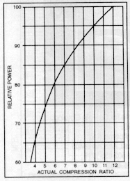
Graph 1 - Let's look at this compression chart for a minute. Notice the 12 percent power increase obtained by increasing compression from six to nine on the chart. Also, note the smaller five percent increase obtained by upping compression from nine to 12 on the chart. A racer obviously needs every ounce of power that can be extracted, but we mortals are better suited to a mildly compressed motor which will last several seasons. The following chart illustrates the effect that engine displacement and octane have on suggested compression ratios.
![]()
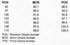
Do not make the mistake of using the wrong octane rating system. There are several different methods of obtaining octane ratings. The following chart shows the difference in the three most common octane rating systems.
It is important to use the proper method when designing combustion chamber ratios. I personally calculate the compression ratio geometrically. Some tuners use compression gauge readings when designing compression chambers. This could become a very costly operation because cranking compression depends a great deal on the condition of the cylinder bore, piston, and rings. Let's say your compression gauge reads 210 pounds. So you calculate that to be 210/14.7 = 14.28:1. This may or may not be the true compression ratio.
Now, let's say you bore your cylinder and replace your piston and rings, and now your cranking compression rises to 235 pounds. Your compression ratio is now 16:1. A compression gauge should be used only to monitor the condition of your bore and to detect a loss of compression as normal wear occurs. Always use the same compression gauge when making routine compression checks. When your motor is fresh and running at its peak, record the compression reading. Use this as your starting point. As wear occurs, your compression will obviously decrease. But this decrease may indicate potential problems. Monitor your engine, and act on your observations. For example, if your compression drops 10 pounds, you may or may not need to replace rings and/or pistons, but you should check them out.
The correct method to determine compression ratios involved the use of geometric formulae. I calculate cylinder volume when the piston is at bottom dead center (BDC) and head volume when the piston is at top dead center (TDC).
Cylinder volume formula:
Bore x bore x stroke x 0.7854 + volume
Compression ratio formula:
Head volume + Cylinder volume/head volume
Example: a 550 Kawasaki jet Ski has a standard bore of 75mm, a stroke of 60mm, and a combustion chamber volume of 24cc. First, convert mm to cm.
7.5 x 7.5 x 6.0 x 0,7854 = 265.0725cc for each cylinder.
24cc + 265.0725cc = 289.0725/24 = 12.04:1 ratio
Squish band clearance is an important factor in obtaining the proper burn pattern of the fuel/air mixture. A squish band clearance that is too large will cause loss of power and possible overheating. A too small squish band will cause engine damage. The following chart shows recommended squish band clearances:
Cylinder Vol (cc) Clearance (mm'$)
50-80 0.6-0.8
100-125 0.7-0.9
175-250 1.0-1.4
300-500 1.1-1.5
Ignition timing affects combustion chamber temperatures. The following illustrates how advancing the ignition raises engine temperature.
Advance (mm) Temp (Celsius)
2.00 853
2.25 876
2.50 908
2.75 962
As you can see, small timing changes have a big effect on operating temperatures. Timing changes must be approached with great caution. If in doubt, leave it at the stock position. Excessively high operating temperatures cause destruction of pistons, rings, and even cranks. If ignition work is to be performed, it must be done by someone capable of reading and understanding plugs and piston tops.
Graph 1 Graph 2 Graph 3
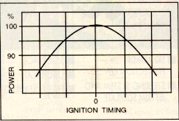
Graph 2 - This graph shows that the most power is produced when ignition timing is spot on. When timing is off in either direction, trouble begins by either heat detonation or pre-ignition. It is safer to run your ignition slightly retarded than advanced too far. Never use someone else's ignition settings. Each machine has its own characteristics, and by using someone else's data, you run a great risk of engine failure.
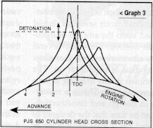
Graph 3 - This drawing shows pressure buildup due to combustion which is added to the mechanically inducted compression already in place. Point 1 shows retarded timing which will increase heat and reduce power. Point 2 is better and normal for most engines. Point 3 is close to optimum, but it is at the point where detonation may begin. Point 4 is where problems really begin to surface. The engine is detonating, causing peak cylinder pressure before TDC. This results in loss of power because the higher pressures are trying to make the engine rotate backwards. The trick is to find a point somewhere between points two and three Remember, the point of detonation is not fixed. It varies with different fuels, barometric pressure, air temperature, engine compression, and timing.
Precision in building top end power is critical. If you slip in the least, disaster is imminent. Seizures happen for many reasons, and by studying your seized pistons, you can often discover the cause of your problems.
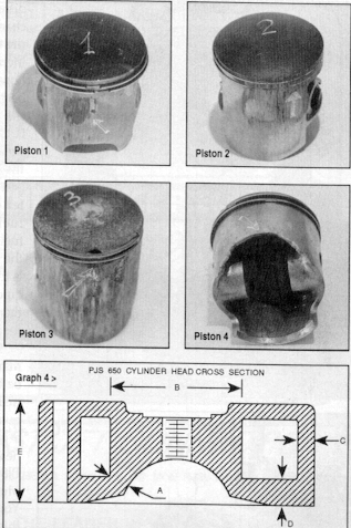
Piston 1 - The first piston shows partial seizure due to over-cooling or lean carburetion at high speed. In this case, the engine will stop momentarily at high speed, then restart and go, but full power will never be delivered by this cylinder. What makes this interesting is that cranking pressure will show normal psi, but power delivery will decrease. The only solution to this problem is visual inspection. In order to detect this kind of problem, make sure the rings did not get stuck in the grooves.
Piston 2 -The second piston shows a more severe seizure. The difference is that the rings got stuck, so this cylinder will show a reduced cranking pressure.
Piston 3 - The third piston represents the worst case of meltdown due to improper cooling, ignition timing, water in cylinder, a low octane fuel, piston clearance or not enough oil. This will result in both cylinder and connecting rod damage.
Piston 4 - The final piston indicates skirt cracking due to too much piston-to-bore clearance, resulting in busted lower cases, crank, cylinder and head.
Proper cooling of the engine is very important. Modified engines operate at higher temperatures than stock. Cooling water must be provided in proper amounts. More is not always better, though. Too much water flow at lower water temperatures and high speed (WOT) will cause seizures. Insufficient water flow at higher water temperatures will cause piston meltdown.
Another factor which affects combustion is carburetor size and amount of fuel flow through the cylinders, The following chart shows the effects of fuel flow on combustion temperature.
Fuel Flow (Litres/hr) Spark Plug ElectrodeTemp (Celsius)
3.00 905
3.25 880
3.50 855
3.75 835
4.00 800
4.25 765
Proper spark plug selection is yet another factor in engine performance. The heat range of the plugs must be selected to suit the type of riding that will take place. Long straight-aways require a colder plug, while short runs need a hotter plug.
Spark plug gap must be correct for any given situation. Higher compression motors should have their plugs gapped smaller. This allows the plug to fully ignite the mixture. Often, changing a gap by only 0.002" will make the difference between a well-running machine and a poorly running machine. The following chart shows the effect of spar plug heat ranges on plug temperatures:
Plug Type (NGK) Under Plug Temp (Fahrenheit)
N7 265
N8 255
N9 245
N10 235
Head modifications must be performed a qualified machinist. You can create any shape combustion chamber by using trigonometry (X, Y, Z coordinates) and the incremental cutting technique. This picture (Photo A) is a Kawasaki 650 head. As you can see, the combustion chamber is quite different from stock. By making the chamber into more of a hemi-head configuration, reasonable compression increases can be made. Please note how precisely the gasket surface has been machined. If you can't machine the mating surfaces to within 0.0002", leakage will undoubtedly occur. In the drawing below, notice the bell-shaped combustion chamber. This is designed to promote better combustion with lower octane fuels. When using higher octane fuels, a hemi-head combustion chamber is the better choice. The reason for this is that lower octane fuels bum much quicker than higher octane fuels and therefore more piston area is needed for proper energy transfer.
Graph 4 - When selecting an aftermarket head, your selection should be based upon the amount of modification desired. There are several quality aftermarket heads that allow a great deal of modification. The head shown in this drawing is for a PJS Kawasaki 650. This is a masterpiece in design and construction. You can be sure that the designer of this head has a total knowledge of two-stroke engine technology. Consider the outline points of this cross section and you will soon become a believer in its quality.
Dimension A: This is approximately 0.035" thick. A properly designed combustion chamber which allows for increasing or decreasing compression.
Dimension B: This spark plug boss is 2.062" in diameter, offering the strongest possible support.
Dimension C: The outside wall thickness is 0.150" which offers sufficient support for both eight and 14mm bolts.
Dimension D: This is the most important factor when considering the quality of a head's design. Most problems occur due to insufficient material strength in this area, which in turn causes vibration at high rpm and increased pressure. Many seizures are caused by leakage in this area.
Dimension E: This head has a height of 1.7", making it the thickest around. Its cooling capacity is approximately 250ccs, which is sufficient for sustained high rpm operation.
Overall, the entire inside and outside is finished with a high quality plating which offers excellent protection from the elements.
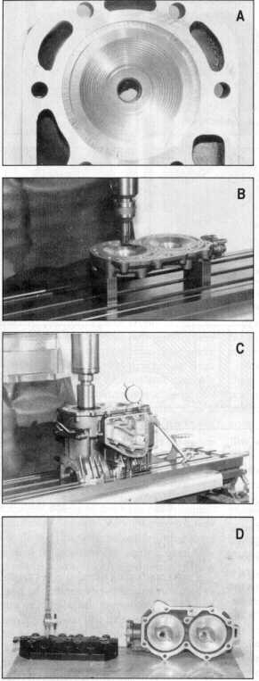
Photo B - Building high performance engines requires precision in every detail. Symmetry of gas flow in each cylinder is accomplished with extreme accuracy. Begin the work of transferring cylinder bore centerlines to the head by scribing its diameters, and then locating the center of each bore on the milling machine. This process allows precise volume matching in multi-cylinder engines.
Photo C - Before any compression changes are made, you must make sure that your piston, rings, and bore are in good shape. Cylinder boring must be performed accurately. Any out of round bore, or bore that is not parallel to the crank and connecting rod's travel will greatly diminish engine performance. I have seen freshly bored cylinders which are crooked or tapered as much as 0.004". VVhen examining the piston, you will notice shiny spots in the direction of intake and exhaust ports. This is normal due to piston slap at the bottom of its travel. However, if either side of the piston has shiny spots, something is wrong. Any such situation must be corrected immediately.
Photo D - The precision of combustion chamber volume is very important. In race motors, I machine the tops of the pistons just enough to make them the same height from the wrist pin centerline. Then the chamber volume is measured. My tolerance between chamber volumes is 0.3cc in a race motor and 0.5cc in a recreational motor. Stock motors can vary by as much as 0.8cc. This inaccuracy is not acceptable in a modified engine.
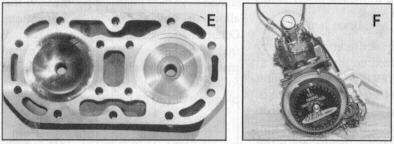
Photo E - In this picture, notice the right side chamber. It was machined using the X, Y, Z trigonometry I mentioned earlier. On the left side is the same chamber polished to a mirror finish. By having a highly polished chamber, the top of the piston and exhaust temperature will be lowered considerably. This allows higher compression ratios and promotes longer piston, ring, and bore longevity.
Photo F - All of your expensive engine mods can be wasted if the engine is not tested for leakage before operation. Do not even think about starting your motor if it was not pressure tested! This picture shows how most shops pressure test their motors. After plugging the intake and exhaust, the engine is either pressurized or vacuum evacuated to about 20 psi. We are looking for a maximum loss in pressure of one to two psi per minute. If the motor leakage rate is greater than that, we know that a problem exists and must be corrected. If not corrected, a lean condition may exist which will result in either piston seizure or great difficulty in jetting your carburetor. However, this procedure is not fool-proof. It does not show leakage through the head gasket at combustion pressures. To detect head gasket leakage at higher pressures, I've developed the following procedure.
First, construct backing plates 1/2" thick to be used in blocking off the exhaust and intake ports. Also, cut out gaskets for these backing plates from 1/8" stiff rubber. Assemble the cylinder head using the new gasket and torque to specification. If your cylinder head has two outgoing water lines, plug one of them off. Attach an air hose to the remaining water line fitting. Turn the cylinder with the bottom facing up and fill the bores with lightweight oil up to the exhaust port. Use a pressure regulator on your air compressor and begin to pressurize the water jacket. Begin with 20 psi and work up in 10 psi increments. Usually, half of the heads will show small air leaks into the cylinder bore at around 50 psi. This is tolerable for a stock machine, but in a highly modified machine, this spells trouble. I myself test all top ends at 200 psi using Argon gas from my tig welder. This way I am assured that no leakage will occur in the future.
Another benefit of high pressure testing is the detection of porous heads and cylinder liners. Not all castings are perfect and this is the only safe way to detect such imperfections. Obviously, when applying such great pressures to your cylinder, safety becomes paramount. I perform all my testing behind the safety of a concrete wall, just in case.
This may seem like a lot of unnecessary work, but.let me assure you, it's worth it. I have never had a seizure due to water leakage into the combustion chamber. Truly successful engine mods are only possible when all details are perform faithfully.
George Grabowski HPT Sport USA