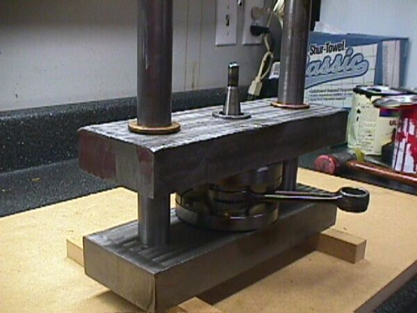
Q. Who builds and where do you buy the tools to rebuild crankshafts?


Reply
A large surface plate to put everything on to get better readings. Might also want to look at Bench Centers... these are very
expensive and heavy but some have less than .00015 run-out. Check www.rutlandtool.com on their 2004 online catalog
under page 637.

Reply
there are special die sets that will hold the parts in pretty good alignment when you press them together. I can't remeber the
site where that type of thing is sold. but i know the small engine shops buy them. it is a precsion die set that comes
with bushings that will align the crank wheel and hold them perfectly perpendicular to the shafts while you are pressing them.
They also will hold both halves timed so that when your done pressing there isn't as much wooden hammer work to get the
halves timined perfectly.


Here's a couple of pictures of a crank assembly and alignment jig that I built for single cylinder engines. Works great....
cost me about $25 in material and a weekend of time to make. Once assembled... crank alignment is under .0005 in all
planes and requires no additonal hammering.
The alignment rods are 1" stainless and the crankcenter dies are 4130...heavy sucker when done as the top and bottom
are made out of 1018 that I found at a salvage yard.
A comparable store bought one cost in the neighborhood of $700.


First of all you must have a good quality press with enough power to allow precise control. While a press under 30 tons will sometime
work it will not give you the control that you need to get the precise rod clearance that we will be looking for. The framework of the
press needs to be strong and heavy also. I use a 30-ton and wish I had a 50-ton on some jobs.

The first step is to clean up the crank and give it a good inspection. Pay close attention to the main bearing journals and the crank
ends as people like to beat on them, instead of using the correct tools to remove the crank from the cases. Check the flywheel
thread to make sure they are ok. Measure the main bearing journals to make sure they are within specs. You don’t want to go
through the rebuild process and find out after the fact that something is screwed up.

Now take a machinist square and scribe lines across the outer edges of the crank in at least two places. I do three that are
about 120° apart. You will use these lines as references when you go to reassemble the crank. I then measure the assembled
crank width with a micrometer to see what that distance is. I normally measure it at the same points that I scribed the alignment
lines. This measurement will determine the amount of crankshaft endplay and also the rod side clearance. Compare this number
 to your service manual specification and write it down. I also like to look at how the rod pin is placed in the crank web to see if it is
flush with the edge or recess slightly. This will give me a reference on the depth to install the new pin. If the rod pin has been spot
welded, now is the time to grind out the weld.

Now it’s time to press this sucker apart. I like to heat up the flywheels with a propane torch as it expands the flywheels a small
amount and makes the rod pin removal a little easier. I have a one inch steel plate that has a center hole and several holes of
different sizes around the center hole that will give the rod pin a place to go when you press it out. Now take an old rod pin that
is smaller than the one you are removing to use as a press pin, make sure everything is lined up and start pressing the pin out.

Normally you will hear a loud pop when the pin starts to move. Continue pressing until the top flywheel is free… remove it along
with the rod, rod bearing and thrust washer and continue pressing until the rod pin comes out the bottom.
Some people use a metal piece to insert between the flywheel, which is shaped like a “U” to keep the pressure off of the rod and
thrust bearings. This is a good idea if you are going to reuse the rod and just replace the bearing, pin and thrust washers. I do not
ever re-use the rod, or any of the other parts, so I just press the sucker apart as it sets.
Ok…. clean the flywheels up again and check to see if the rod pin journals are not scored. Lay out everything on a clean towel
in the order of reassembly. That would be… a flywheel, new rod pin, thrust washer, rod bearing, thrust washer and flywheel. I put
a light coating of assembly lube on new parts. Now heat up the flywheel again and cool the rod pin, this makes the pressing
process much easier and allows you a lot more control when pressing it together. Carefully align the pin and press it in place.
Let the assembly cool back down and we are ready to put on a thrust washer, the rod and bearing assembly and the outer thrust
 washer. Sometimes I will place the flywheel and pin that I just pressed together in the freezer to help cool them down quicker and
also shrink them slightly.

Now it’s time to get out the alignment jig that I built and select the correct size inserts that fit the crank that I’m rebuilding.
The already pressed together flywheel assembly with the thrust washers and rod are placed in the bottom part of the jig.
 Now it’s time to heat up the top flywheel, and then using a machinist square, align the marks that I made way back in the
first stage of this process, to bring the two halves into close alignment. Put everything back into the press and carefully start
the pressing process. The press is now applying pressure to the jig and with the design of the jig being such that the every
 thing is centered around the crank journals it will only go together… square and in perfect alignment. That is assuming that
your jig was made with tender loving care and is within .0005 itself. The final alignment will only be as good as the precision
of the jig.

Now we need to be concerned about the rod clearance as we continue pressing the crank together. There are two ways to go
about this… either continue pressing until the crank width matches the specs, or use a feeler gage. I like to use both as a check
against each other.

Remove the crank assembly from the jig and measure the crank width around the clock. They should all be the same if it’s perfect
and certainly within .0005 if my jig is cool. This tells me that the crank halves are parallel. Now I put the assembly on two “V” block
 that are set on a surface plate…set up a couple of dial indicator at locations on the crank journals recommend by the manufacture
and slowly rotate the crank to check for twist. Again if my jig is doing its thing it will be less than .0005 TIR… .0005 TIR means that
 in reality the crank is within .00025 from prefect zippo.

These specs are pretty cool the way they are and will provide a sound crank. If you want to micro true the crank, then find the
high spot and while holding the opposite halve in your hand, rap it with a brass hammer and retest. It really doesn’t take much
of a rap to move the crank a bunch. It’s a touchy, feely thing, which will in some cases really work on your patience. I like to set
the crank aside till the next day, because sometimes I’ve found that when it ages for a while it will sometimes change ever so
slightly. This may be true… whether you use a jig, or use the eyeball, “V” block, hammer method.

Normally after installing using the jig… it’s good to go, without any final adjustment needed!!!!

Hopefully the pictures will help shed a little light on the subject. As you can see the jig is getting a little shop worn and
cosmetically is getting tired. But it’s 15 years old and has gone through hell and a bunch of cranks…but it still works.
When and if I build another, I’d do it the same way and just make it a little prettier next time. At the time I built it I was in
a major time constraint and just needed something that would be accurate.
Your mileage may vary and as with anything, there are more than one way to do a process. This one works for me.