Below is part of a suspension conversation I had a few years back on this subject, it was lost in my archives and I just found it.
LONG TRAVEL SUSPENSION MODIFICATION FOR FL400
1) PURPOSE:
This investigation is a brief look at the effect of increasing the suspension travel of the FL400 (Pilot). The basic assumptions are that the A-arms, cushions and steering mechanism will be modified with the frame mounting locations and the knuckle left as is. This investigation dose not try to rectify the front suspension geometry w.r.t. handling performance.
It should be kept in mind that this investigation is a brief look at a complex system. Many items are glossed over and there is no engineering review of the recommendations made. Furthermore there is no attempt to calculate the strength or fatigue life of any of the modifications discussed. I have made this investigation on my own for possible use on my own vehicle at some future date and it has no connection to my employer. Any action taken based on the information reported here is taken at the owner / fabricator’s risk. Please do not share this with anyone who dose not have the brains to understand this.
2) BASIC ASSUMPTIONS:
1.Modify a stock FL400 for increased front suspension travel.
2.Frame and knuckle remain stock.
3.Steering system is modified to reduce bump steer and maintain functionality (modifications to increase suspension travel may interfere with tie rods).
4.A-arm lengthened 2 to 2.5 inches.
5.10” of front travel is the target.
6.New cushions from an after market source.
3) CONCLUSION
1)2.5” longer A-arms. Consider some type of adjustment to the upper arm length to set the static camber.
2)Move the ride hight up 2”. 1” is achieved by moving the 1G setting of the suspension, 1” is achieved by a larger front tire.
3)As stated above change to a 24” tire.
4)Some method of reducing the bump steer is needed
4) BASE MODEL TO START INVESTIGATION
The original vehicle was designed in 2D. The base layout dose not show the suspension in detail in the side and top views. Therefore some assumptions where made about the steering ball joint stud angles. As this investigation is limited to the basic layout so this should not be a problem.
5) LENGTH OF ARMS
To find the effect of the length of the A-arm the first modification was to make the A-arms 2” longer. From this model it was apparent that the ball joint stud angles would be significantly more than the stock vehicle at a wheel travel of 10”.
The 2nd model has 2.5” longer A-arms. On this model the ball joint stud angles are still much larger than the base vehicle but possibly acceptable.
This should be seen as the minimum acceptable A-arm length for 10” of wheel travel based on the ball joints and cushion function. Longer arms will improve the suspension wheel geometry but the rear track of the vehicle should be adjusted if the front is made wider than +5 inches.
6) BALL JOINTS
At +2.5” arms and 10” of wheel travel the ball joint maximum angle will look like this:
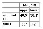
It could be possible to use 400EX ball joints, however this would require that they be cut out of the existing arms as they are not available separately. It should be noted that the range of motion used is very large compared to what is typical of ATVs. Care is needed in the orientation of the ball joints to insure they do not bottom out. Ideally they should have an equal ‘margin’ all the way around in case of miss-calculations, fabrication errors or flex in the system. Also remember that most cushions have some amount of over stroke, you can see the bump rubber for compression but there is (usually) an internal spring for the fully extended condition.
7) RIDE HIGHT
There are several factors that need consideration to set the ride hight.
1)Bump stroke limitations. It may be possible to increase the bump stroke 15mm (0.6”).
a)This is not much of a change but it maintains the performance of the vehicle in full bottoming events. Catching the frame while landing a jump is not a good thing. The limp home with 2 flat tire capability may be compromised but gaining some bump travel is desirable (this should allow limping home at a slower pace, you don’t want to compress the suspension to the point that the frame drags).
b)Shock length limitations. I have assumed that the stock frame side shock mount would be used. Also I have assumed that the new A-arm would mount the shock the same distance from the lower ball joint as the stock arm. With this placement the collapse length of the shock is 0.5 to 0.75 inches too short. It should be possible to mount the lower end of the cushion below the level of the stock configuration by allowing the cushion to pass threw the A-arm. More on this in section 7.
2)Suspension geometry.
a)If the suspension travel is increased to 10”, mostly in the rebound direction the ride hight will end up at approximately the centre of the stroke. This is typical for passenger cars operating on smooth roads with an emphasis on comfortable ride character. By moving the ride hight up 2” the bump stroke is approximately 2/3 and the rebound is 1/3. This is more reasonable for good off road trail performance.
b)The suspension geometry is not too bad at this position however increasing the tire size to a 24” tire would improve the over all geometry (see section 8). With a 24” tire the ride hight is increased 1” by the tire and 1” by the spring setting.
8) CUSHIONS
The assumptions for the cushion mounting locations were discussed above in 6.1.b.
1) I believe the shortest possible shock would be in the range of 286mm (11.25”) at full bottom and 431mm (17”) at full extension. It is at the very shortest length available for Showa M/P shocks. My older Works catalogue says Steelers can be made to this spec. It may be desirable to move the lower shock mount down to allow the use of a longer and easier to obtain shock.
2)There needs to be some consideration for the actual length of the shock. I would recommend having the shocks in hand before finalizing the lower shock mount. This way small adjustments can be made to insure the travel is a full 10” but not more as that could cause problems with the ball joints.
9) SUSPENSION GEOMETRY
The following areas of the suspension geometry deserve some discussion. In this analysis no layout adjustment was considered to improve the suspension geometry. Rather the A-arms where lengthened and the result analysed to see if some items become unmanageable.
1)Scuff or ground contact
a)Moving the ride hight dose not affect the amount of side movement of the ground contact point as the suspension is stroked, simply the “0” position is moved.
b)The stock Pilot has a one side scuff of about 23mm. This compares favourably with the 400EX at 25mm (400EX has more suspension travel). The modified Pilot has a scuff of 59mm (+2.5” arms and 10”travel, move ride up 2” and stock tires). This is a big increase and could adversely affect control and predictability in jump landing or other events where both wheels see a large stroke.
c)To improve this the effect of a larger tire was looked at. As the suspension is stroked the contact patch moves away from the centre line of the vehicle. At the top of the stroke the contact patch is starting to move back in to the centre of the vehicle. A larger tire would move the usable range of the stroke up to an area where the wheel moves out then back in, effectively reducing the overall scuff.
d)With a 24” tire the scuff is reduced to 37mm. The camber change is larger than stock but probably acceptable, see 8.2. As the improvement was so dramatic a 26” tire was looked at also.
e)With a 26” tire the scuff is 44mm. With the 26” tire the ride hight adjustment is made with the tire and the suspension is allowed to stroke up an additional 2” from stock. As the suspension strokes up the shorter upper arm starts to pull the top of the tire in faster than the lower arm. The result is an increase in camber change. With the 26” tire the camber at full bump is 5 degrees, with the 24” tire it is 2.7 degrees. This is not advantageous therefore I recommend the 24” tire.
2)Camber change during suspension stroke.
a)The camber change in suspension stroke is almost equal in bump (-2.3˚ ) and rebound ( -2.1˚ ) with the static ride hight camber 0˚.
b)Reducing rebound camber change would improve stability. The 400EX rebound camber is -1.6˚ and the stock FL400 is -0.3˚ (very good). The rebound camber affects the stability in straight line (high speed) and initial control in landing jumps. Due to the imitations of this investigation there was no effort made to improve this condition, however it should be within the acceptable range.
c)The camber in bump is good. Negative camber in bump improves traction in cornering although this is a small effect as ATV type tires are rounded. This effect is much more important in road cars.
3)Toe change
a)The stock FL400 has a toe change of 30mm for each side, the 400EX 31mm. The proposed modifications to the Pilot would have a one side toe change of 72mm ( 56mm at bump and 55mm at rebound, 6mm negative in-between). This is on the excessive side.
b)Rebound toe change is detrimental to driving stability.
c)Some method to reduce this is needed and was assumed from the beginning of the investigation.
http://www.PilotOdyssey.com

 PilotOdyssey.com Chat
 PilotOdyssey.com Google Search
 FL400 Parts
 FL350 Parts
 FL250 Parts
 Admin Email

